


556454-YTG-A-0210
2 Johnson Controls Unitary Products
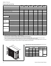
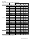
All dimensions are in inches. They are subject to change without notice.
Certified dimensions will be provided upon request.
.
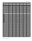
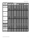
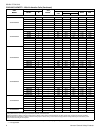
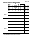
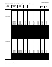
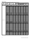
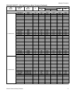
Physical and Electrical Data
MODEL
TCHD18
S41S3
TCHD24
S41S3
TCHD30
S41S3
TCHD36
S41S3
TCHD48
S41S3
TCHD60
S41S3
Unit Supply Voltage 208-230V, 1 60Hz
Normal Voltage Range
1
187 to 252
Minimum Circuit Ampacity 11.8 17.4 17.5 23.1 27.1 34.3
Max. Overcurrent Device Amps
2
20 30 30 40 45 60
Min. Overcurrent Device Amps
3
15 20 20 25 30 35
Multi-Stage Compressor No No No No No No
Compressor Type Scroll Scroll Scroll Scroll Scroll Scroll
Compressor Amps
Rated Load 9.0 13.5 12.8 17.3 20.5 26.3
Locked Rotor 48.0 58.3 64.0 96.7 115.0 134.0
Crankcase Heater Yes Yes Yes Yes Yes Yes
Fan Diameter Inches 17.5 17.5 23 23 23 23
Fan Motor
Rated HP 1/8 1/8 1/4 1/4 1/4 1/4
Rated Load Amps 0.60 0.60 1.45 1.45 1.45 1.45
Nominal RPM 840 840 850 850 850 850
Coil
Face Area Sq. Ft. 5.76 5.76 11.96 11.96 13.96 13.96
Rows Deep 1 1 1 1 1 1
Fins / Inches 23 23 23 23 23 23
Refrigerant Lines
4
Max. Length 200 200 200 200 200 200
Max. Lift 65 65 65 65 65 65
Max. Drop 150 150 150 150 150 150
Liquid Line Set OD (Field Installed) 3 / 8 3 / 8 3 / 8 3 / 8 3 / 8 3 / 8
Vapor Line Set OD (Field Installed) 3 / 4 3 / 4 3 / 4 3 / 4 7 / 8 7 / 8
Unit Charge (Lbs. - Oz.)
5
2 - 14 3 - 5 4 - 0 4 - 8 5 - 5 5 - 6
Charge Per Foot, Oz. 0.68 0.68 0.68 0.68 0.70 0.70
Operating Weight Lbs. 130 135 195 215 240 250
1. Rated in accordance with ARI Standard 110, utilization range “A”.
2. Dual element fuses or HACR circuit breaker. Maximum allowable overcurrent protection.
3. Dual element fuses or HACR circuit breaker. Minimum recommended overcurrent protection.
4. When more than 50 feet of interconnecting tubing and more than 30 feet of vertical lift is used, consult the Application Data (part number
247077). For long-line applications, interconnecting lines over 100 feet must be installed with liquid line solenoid.
5. The Unit Charge is correct for the outdoor unit, matched indoor coil and 15 feet of refrigerant tubing. For tubing lengths other than 15 feet, add
or subtract the amount of refrigerant, using the difference in length multiplied by the per foot value.
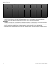
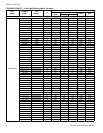
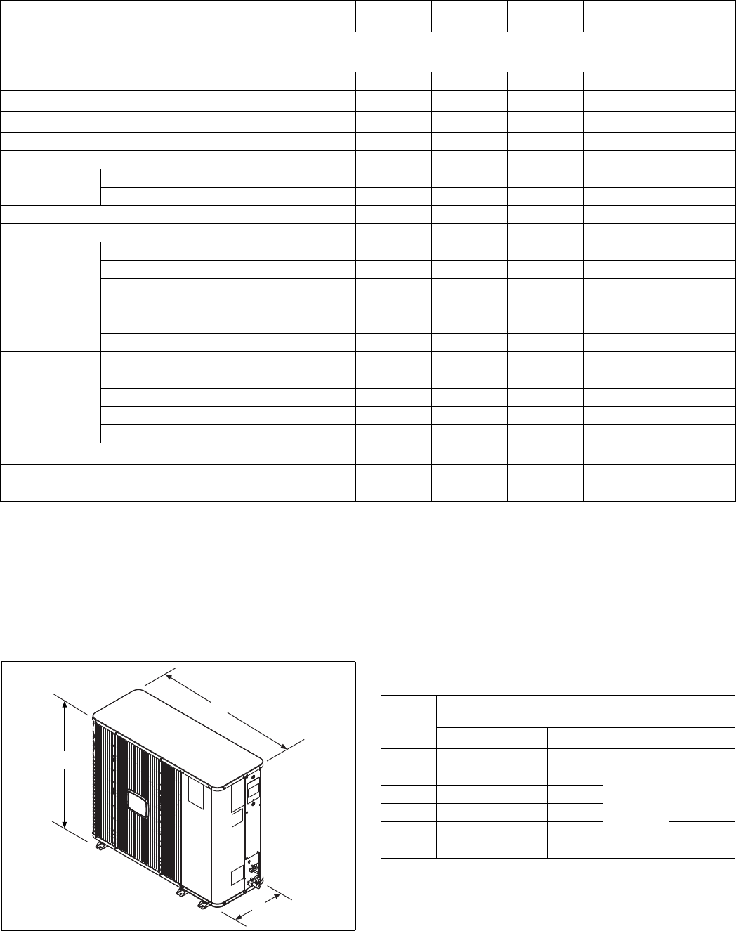
B
C
A
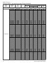
Unit
Model
Dimensions
(Inches)
Refrigerant Connection
Service Valve Size
A
1
1. Including Fan Guard.
B C Liquid Vapor
18 25-1/8 14-5/8 37
3/8”
3/4”
24 25-1/8 14-5/8 37
30 37-1/8 17-1/8 44-5/8
36 37-1/8 17-1/8 44-5/8
48 43-1/8 17-1/8 44-5/8
7/8”
60 43-1/8 17-1/8 44-5/8