R-410A
AFFINITY SERIES
DEX024-048
DEY060
2-5 Ton
GZKDJRRJDGHZ2[JZFJR
288429-YIM-A-0307
TABLE OF CONTENTS
General . . . . . . . . . . . . . . . . . . . . . . . . . . . . . . . . . . . . . . . . . . 1
Installation . . . . . . . . . . . . . . . . . . . . . . . . . . . . . . . . . . . . . . . . 3
Limitations. . . . . . . . . . . . . . . . . . . . . . . . . . . . . . . . . . . . . . 3
Location. . . . . . . . . . . . . . . . . . . . . . . . . . . . . . . . . . . . . . . . 4
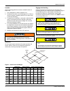
Rigging And Handling . . . . . . . . . . . . . . . . . . . . . . . . . . . . . 4
Ductwork . . . . . . . . . . . . . . . . . . . . . . . . . . . . . . . . . . . . . . . 7
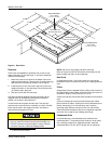
Roof Curb . . . . . . . . . . . . . . . . . . . . . . . . . . . . . . . . . . . . . . 7
Filters . . . . . . . . . . . . . . . . . . . . . . . . . . . . . . . . . . . . . . . . . 7
Condensate Drain . . . . . . . . . . . . . . . . . . . . . . . . . . . . . . . . 7
Service Access . . . . . . . . . . . . . . . . . . . . . . . . . . . . . . . . . . 8
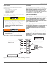
Thermostat . . . . . . . . . . . . . . . . . . . . . . . . . . . . . . . . . . . . . 8
Power And Control Wiring. . . . . . . . . . . . . . . . . . . . . . . . . . 8
Compressors. . . . . . . . . . . . . . . . . . . . . . . . . . . . . . . . . . . 11
Phasing . . . . . . . . . . . . . . . . . . . . . . . . . . . . . . . . . . . . . . . 12
Airflow Performance . . . . . . . . . . . . . . . . . . . . . . . . . . . . . . . 12
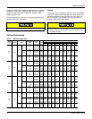
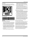
Blower Speed Selection . . . . . . . . . . . . . . . . . . . . . . . . . . 17
Operation . . . . . . . . . . . . . . . . . . . . . . . . . . . . . . . . . . . . . . . 18
Cooling Sequence Of Operations . . . . . . . . . . . . . . . . . . . 18
Heating Sequence Of Operations. . . . . . . . . . . . . . . . . . . 18
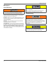
Maintenance . . . . . . . . . . . . . . . . . . . . . . . . . . . . . . . . . . . . . 20
Normal Maintenance. . . . . . . . . . . . . . . . . . . . . . . . . . . . . 20
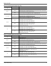
Troubleshooting . . . . . . . . . . . . . . . . . . . . . . . . . . . . . . . . . . 20
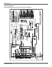
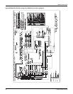
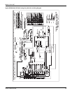
Typical Wiring Diagrams . . . . . . . . . . . . . . . . . . . . . . . . . . 21
LIST OF TABLES
1 Unit Limitations . . . . . . . . . . . . . . . . . . . . . . . . . . . . . . . . . 3
2 Unit Accessory Weights . . . . . . . . . . . . . . . . . . . . . . . . . . 5
3 Unit Dimensions Front. . . . . . . . . . . . . . . . . . . . . . . . . . . . 5
4 Unit Clearances. . . . . . . . . . . . . . . . . . . . . . . . . . . . . . . . . 5
5 Electrical Data . . . . . . . . . . . . . . . . . . . . . . . . . . . . . . . . . . 9
6 Physical Data . . . . . . . . . . . . . . . . . . . . . . . . . . . . . . . . . 10
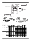
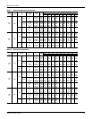
7 Side Duct Application . . . . . . . . . . . . . . . . . . . . . . . . . . . 12
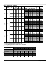
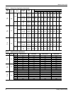
8 Bottom Duct Application . . . . . . . . . . . . . . . . . . . . . . . . . 13
9 Additional Static Resistance . . . . . . . . . . . . . . . . . . . . . . 14
10 Electric Heat Minimum Supply Air. . . . . . . . . . . . . . . . . . 15
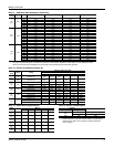
11 Indoor Blower Specifications. . . . . . . . . . . . . . . . . . . . . . 15
12 Electric Heat Multipliers . . . . . . . . . . . . . . . . . . . . . . . . . 15
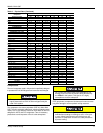
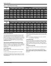
13 DEX024 Superheat Charging . . . . . . . . . . . . . . . . . . . . . 16
14 DEX030 Superheat Charging . . . . . . . . . . . . . . . . . . . . . 16
15 DEX036 Superheat Charging . . . . . . . . . . . . . . . . . . . . . 16
16 DEX042 Superheat Charging . . . . . . . . . . . . . . . . . . . . . 16
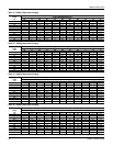
17 DEX048 Superheat Charging . . . . . . . . . . . . . . . . . . . . . 17
18 DEY060 Superheat Charging . . . . . . . . . . . . . . . . . . . . . 17
19 Delay Profile . . . . . . . . . . . . . . . . . . . . . . . . . . . . . . . . . . 18
20 Thermostat Signals (Single Phase Units) . . . . . . . . . . . . 19
21 Thermostat Signals (Three Phase Units) . . . . . . . . . . . . 19
LIST OF FIGURES
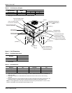
1 Component Location . . . . . . . . . . . . . . . . . . . . . . . . . . . . 3
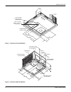
2 Unit 4 Point Load Weight . . . . . . . . . . . . . . . . . . . . . . . . . 4
3 Unit Dimensions. . . . . . . . . . . . . . . . . . . . . . . . . . . . . . . . 5
4 Dimensions Front and Bottom . . . . . . . . . . . . . . . . . . . . . 6
5 Dimensions Back and Bottom . . . . . . . . . . . . . . . . . . . . . 6
6 Roof Curb. . . . . . . . . . . . . . . . . . . . . . . . . . . . . . . . . . . . . 7
7 Typical Field Control Wiring Diagram Single Stage
Thermostat. . . . . . . . . . . . . . . . . . . . . . . . . . . . . . . . . . . . 8
8 Typical Field Control Wiring Diagram 2 Stage
Thermostat. . . . . . . . . . . . . . . . . . . . . . . . . . . . . . . . . . . . 9
9 Typical Field Power Wiring Diagram . . . . . . . . . . . . . . . . 9
10 Control Board Speed Tap Location . . . . . . . . . . . . . . . . 18
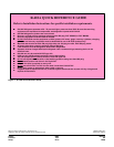
11 R-410A Quick Reference Guide . . . . . . . . . . . . . . . . . . 24
General
YORK
®
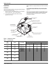
Affinity Models DEX and DEY units are factory
assembled cooling units designed for outdoor installation on a
roof top or a slab. Field-installed electric heater accessories are
available to provide supplemental electric heat combined with
electric cooling.
The units are completely assembled on rigid, removable base
rails. All piping, refrigerant charge, and electrical wiring is
factory installed and tested. The units require only electric
power and duct connections at the point of installation.
The electric heaters have nickel-chrome resistance wire
elements and utilize single point power connection.
Safety Considerations
This is a safety alert symbol . When you see this symbol on
labels or in manuals, be alert to the potential for personal injury.
Understand and pay particular attention the signal words
DANGER, WARNING or CAUTION.
DANGER indicates an imminently hazardous situation, which,
if not avoided, will result in death or serious injury
.
WARNING indicates a potentially hazardous situation, which,
if not avoided, could result in death or serious injury
.
CAUTION indicates a potentially hazardous situation, which, if
not avoided may result in minor or moderate injury
. It is also
used to alert against unsafe practices and hazards involving
only property damage.
Improper installation may create a condition where the
operation of the product could cause personal injury or
property damage. Improper installation, adjustment,
alteration, service or maintenance can cause injury or
property damage. Refer to this manual for assistance or
for additional information, consult a qualified contractor,
installer or service agency.