


036-21584-001 Rev. B (1004)
Unitary Products Group 5
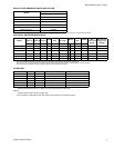
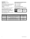
FILTER PERFORMANCE
The airflow capacity data published in the “Blower Perfor-
mance” table listed above represents blower performance
WITHOUT filters. To determine the approximate blower per-
formance of the system, apply the filter drop value for the fil-
ter being used or select an appropriate value from the “Filter
Performance” table shown below.
NOTE: The filter pressure drop values in the “Filter Perfor-
mance” table shown below are typical values for the type of
filter listed and should only be used as a guideline. Actual
pressure drop ratings for each filter type vary between filter
manufacturer.
* Washable Fibers are the type supplied with furnace (if supplied.
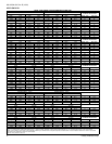
APPLYING FILTER PRESSURE DROP TO
DETERMINE SYSTEM AIRFLOW
To determine the approximate airflow of the unit with a filter in
place, follow the steps below:
1. Select the filter type.
2. Select the number of return air openings or calculate the
return opening size in square inches to determine the
proper filter pressure drop.
3. Determine the External System Static Pressure (ESP)
without the filter.
4. Select a filter pressure drop from the table based upon
the number of return air openings or return air opening
size and add to the ESP from Step 3 to determine the
total system static.
5. If total system static matches a ESP value in the airflow
table (i.e. 0.20, 0.60, etc,) the system airflow corre-
sponds to the intersection of the ESP column and Model/
Blower Speed row.
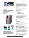
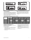
BLK
WHT
GRN
BLK (HOT)
WHT(NEUTRAL)
GRN
NOMINAL
120 VOLT
LINE WIRING CONNECTIONS
SINGLE STAGE HEATING
THERMOSTATCONNECTIONS
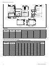
SINGLE STAGE HEATINGAND TWO-STAGECOOLING
THERMOSTAT CONNECTIONS
ROOM
THERMOSTAT
FURNACE
CONTROL
CONDENSING
UNIT
TOAIRCONDITIONER
CONTROLS
R
W
G
Y1
C
R
G
C
COMMONT’STATCONNECTION
Y2
Y1
W1/W
Y/Y2
ROOM
THERMOSTAT
FURNACE
CONTROL
CONDENSING
UNIT
TOAIRCONDITIONER
CONTROLS
R
W
G
Y
C
R
G
C
COMMONT’STATCONNECTION
W1/W
Y/Y2
ROOM
THERMOSTAT
FURNACE
CONTROL
CONDENSING
UNIT
TOAIRCONDITIONER
CONTROLS
R
W1
W2
G
Y2
R
G
COMMONT’STATCONNECTION
Y1
Y1
W1/W
C
C
W2
Y/Y2
TWO-STAGE HEATINGAND TWO-STAGECOOLING
THERMOSTAT CONNECTIONS
FILTER PERFORMANCE - PRESSURE DROP INCHES W.C. AND (KPA)
Airflow Range
Minimum Opening Size
Filter Type
Disposable WASHABLE FIBER* Pleated
1 Opening 2 Openings 1 Opening 2 Opening 1 Opening 2 Opening 1 Opening 2 Opening
Sq. in. Sq. in. In w.c. Pa In w.c. Pa In w.c. Pa In w.c. Pa In w.c. Pa In w.c. Pa
0 - 750 230
0.01 2.5 0.01 2.5 0.15 37
751 - 1000 330 0.04 10 0.03 7.5 0.20 50
1001 - 1250 330 0.08 20 0.07 17 0.20 50
1251 - 1500 330 0.08 20 0.07 17 0.25 62
1501 - 1750 380 658 0.14 35 0.08 20 0.13 32 0.06 15 0.30 75 0.17 42
1751 - 2000 380 658 0.17 42 0.09 22 0.15 37 0.07 17 0.30 75 0.17 42
2001 & Above 463 658 0.17 42 0.09 22 0.15 37 0.07 17 0.30 75 0.17 42