


9
ENGLISH
EN
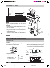
•
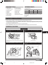
Be careful when handling the sharp edge of the mounting plate.
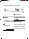
■ Wiring
• This indoor unit is ready for connection to the outdoor unit.
• Never modify the unit by removing any of the safety guards
or by passing any of the safety interlock swithces.
• Connect the interconnecting cable correctly and connect
the connecting cable to terminal as identified with their
respective marking.
•
Do not damage the conductor core or inner insulation of
power supply cables and do not deform or crush the cables.
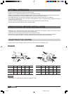
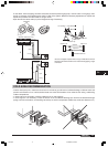
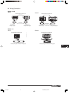
■ Piping
The auxiliary piping can be connected in the diections
shown the above diagram. To connect in the , and
direction, pipes will need to be extended.
• Bend pipes carefully to avoid flattening or obstructing
them if the pipes are bent incorrectly, the indoor unit
may be unstable on the wall.
• Carefully arrange pipes so that pipes do not stick out
of the rear plate of the indoor unit.
A
B
C
D
E
F
MODEL 24
Right
Right
Right
Right
Left
Rear Bottom
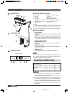
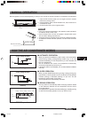
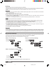
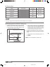
■ Drain hose
• Drain hose is flexible and can be routed to suit various
piping arrangements. The drain line must include elbow
trap (U bend). Connect a plastic condensate pipe with
an internal diameter of 12 mm.
•
The drain hose can be connected to the left or the right side.
Verification of condensate water drainage:
Fill the drain pan with water and observe evacuation.
Note: Do not put the drain hose end into water.
Drain hose
For left and left rear piping
Drain cap
Drain cap
Drain hose
For right and right rear piping
CAUTION
CAUTIONS
CAUTIONS
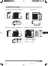
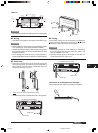
Above 150mm from the ceiling
Hooked Part
Indoor Unit Outline
Hooked Part
Pipe hole
Above 120mm from
the wall
432
58
465
465
115
50
Pipe hole
5850
115
Hooked Part
432
1080
Above 120mm from
the wall
330
108
22
95
95
J199.pmd 31/03/2005, 9:53 PM9