


carrier's agent should be made in writing. See Local Dis
-
tributor for additional information.
LIMITATIONS
These unitsmust be installedin accordance with applicable na
-
tional, local and municipal safety codes.
If components are to be added to a unit to meet local codes,
they are to beinstalled at the dealer'sand/or the customer's ex
-
pense. Refer to Table 1 for Unit Application Data.
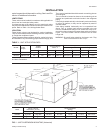
LOCATION
These blower units are not designed for outdoor installation.
They must be locatedwithin the buildingstructure, either inside
or outside the conditioned space.
These Evaporator Blower sections allow forvertical or horizon
-
tal installation in any area offering proper electrical supply, duct
and drain connections.
They may be installed either with ductwork or matching plenum
and inlet grille.
The unit should be located as close to the condensing unit as
practical and positioned to minimize bends in the refrigerant
piping.
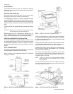
Unitsbeing installed vertically or horizontally can be set directly
on a floor or platform, or they can be supported by metal or
wooden beams.
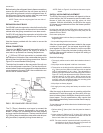
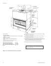
Units being installed horizontally can be suspended from
above. Four
3
8
" (9.5mm) weld nuts are provided in the unit
frame to accommodate hanger rods. Knockouts must be re
-
moved from theunit panels to exposethese weldnuts. Refer to
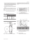
Figure 1 for their location and the individual load on each
hanger rod.
WARNING: Be careful when attaching the hanger rods. They
must not be allowed to turn or slip.
Unitary Products Group 3
550.39-N4YI
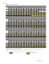
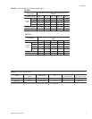
MODEL
Power
Supply
Voltage
Variation*
Supply Air Range
CFM/m
3
/s
Entering Air Temperature, °F(°C)
Cooling-db/wb Heating-db
Min. Max. Min. Max. Min. Max. Min. Max.
KEU090 380/415-3-50 342 457 2400 / 1.3 3600 / 1.7 68/57(20/14) 95/72(18/22) 40(4.4) 77(25)
KEU120 380/415-3-50 342 457 3200 / 1.5 4800 / 2.3 65/57(20/14) 95/72(18/22) 40(4.4) 77(25)
TABLE 1 - UNIT APPLICATION DATA
* Utilization Range “A” in accordance with ARI Standard 110.
INSTALLATION
(66.7).
44-7/8 (1140)
(25.7)
(1251) 49-1/4
(35)
1-3/8
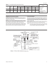
FIG. 1 - UNIT SUSPENSION MOUNTING (Horizontal)
Model
Center of Gravity
Dimensions, (In./mm)
Weight Distribution
(lbs/kg)
A B W1 W2 W3 W4 TOTAL
KEU090 26
1
4
/ 667 23
3
4
/ 603 85 /38.5 93 / 42.2 70 / 32 77 / 34.9 325 / 147.4
KEU120 26
5
8
/ 676 24
1
8
/ 613 85 /38.5 93 / 42.2 70 / 32 80 / 36.2 330 / 149.7