


2 Unitary Products Group
550.39-N4YI
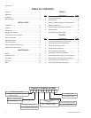
TABLE OF CONTENTS
General
................................................................................
1
Reference
............................................................................
1
Inspection
............................................................................
1
Nomenclature
......................................................................
2
INSTALLATION
Limitations
...........................................................................
3
Location
...............................................................................
3
Clearances
..........................................................................
4
Rigging and Handling
..........................................................
4
Vertical/horizontal Installation
..............................................
4
Duct Connections
................................................................
4
Refrigerant Mains
................................................................
5
Drain Connection
.................................................................
6
Supply Air Blower Adjustment
.............................................
6
Power and Control Wiring
..................................................
11
MAINTENANCE
Filters.................................................................................12
Evaporator Coil..................................................................12
Lubrication.........................................................................12
Drain Pan ..........................................................................12
Belts...................................................................................12
TABLES
No.
Description Page
1 Unit Application Data
............................................
3
2 Physical Data
.......................................................
5
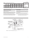
3 Supply Air Blower Motor Pulley Adjustment
.........
7
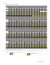
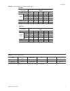
4 Blower Performance
.............................................
8
5 Accessory Static Resistance (IWG/pA)
................
9
6 Electrical Data
......................................................
9
7 Blower Motor and Drive Data
...............................
11
FIGURES
No.
Description Page
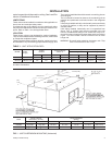
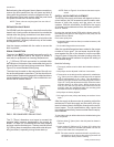
1 Unit Suspension Mounting (Horizontal)
................
3
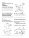
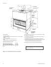
2 Vertical and Horizontal Appplication
.....................
4
3 Supply Air Duct Connection
.................................
4
4 Electric Heater Accessory
....................................
4
5 Recommended Drain Piping ................................ 6
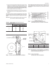
6 Typical Motor Mounting Assembly ....................... 7
7 Pressure Drop Across Dry Coil vs Supply Air ...... 7
8 Hole Locations (Pressure Drop Readings)........... 7
9 Unit Dimensions and Clearances.........................10
10 Typical Field Wiring (Cooling only).......................11
K 4 E U 5 02 A
PRODUCT NOMENCLATURE
PRODUCT GENERATION
4,5 = Design Level
PRODUCT CATEGORY
=Split-SystemEvaporatorBlower with
Motor and Drive
PRODUCT IDENTIFIER
EU = Evaporator Blower Unit
VOLTAGE CODE
50 = 380/415-3-50
NOMINAL COOLING
CAPACITY
090 = 90 Mbh (26.36kW)
120 = 120 Mbh (35.13kW)
FACTORY INSTALLED HEAT
A = Not Applicable
1 0