


Subject to change without notice. Printed in U.S.A. 278436-YTG-A-0407
Copyright © by York International Corp. 2007. All rights reserved. Supersedes: 246771-YTG-C-0706
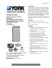
Unitary 5005 Norman
Products York OK
Group Drive 73069
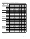
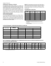
APPLYING FILTER PRESSURE DROP TO
DETERMINE SYSTEM AIRFLOW
To determine the approximate airflow of the unit with a filter in
place, follow the steps below:
1. Select the filter type.
2. Select the number of return air openings or calculate the
return opening size in square inches to determine the
proper filter pressure drop.
3. Determine the External System Static Pressure (ESP)
without the filter.
4. Select a filter pressure drop from the table based upon
the number of return air openings or return air opening
size and add to the ESP from Step 3 to determine the
total system static.
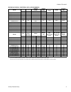
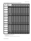
5. If total system static matches a ESP value in the airflow
table (i.e. 0.20 w.c. (50 Pa), 0.60 w.c. (150 Pa), etc,) the
system airflow corresponds to the intersection of the
ESP column and Model/Blower Speed row.
6. If the total system static falls between ESP values in the
table (i.e. 0.58 w.c. (144 Pa), 0.75 w.c. (187 Pa), etc.),
the static pressure may be rounded to the nearest value
in the table determining the airflow using Step 5 or calcu-
late the airflow by using the following example.
Example: For a 60,000 BTUH (17.58 kW) furnace with a bot-
tom return opening and operating on high-speed blower, it is
found that total system static is 0.58” w.c. To determine the
system airflow, complete the following steps:
Obtain the airflow values at 0.50 w.c. (125 Pa) & 0.60 w.c.
(150 Pa) ESP.
Airflow @ 0.50”: 1250 CFM (35.4 m
3
/min)
Airflow @ 0.60”: 1180 CFM (33.4 m
3
/min)
Subtract the airflow @ 0.50 w.c. (125 Pa) from the airflow @
0.60 w.c. (150 Pa) to obtain airflow difference.
1180 - 1250 = -70 CFM (-12 m
3
/min)
Subtract the total system static from 0.50 w.c. (125 Pa) and
divide this difference by the difference in ESP values in the
table, 0.60 w.c. (150 Pa) - 0.50 w.c. (125 Pa), to obtain a
percentage.
(0.58 - 0.50) / (0.60 - 0.50) = 0.8
Multiply percentage by airflow difference to obtain airflow
reduction.
(0.8) X (-70) = -56
Subtract airflow reduction value to airflow @ 0.50 w.c. (125
Pa) to obtain actual airflow @ 0.58 in. w.c. (144 Pa) ESP.
1250 - 56 = 1194
ACCESSORIES
PROPANE (LP) CONVERSION KIT -
1NP0347 - All Models
This accessory conversion kit may be used to convert natural
gas (N) units for propane (LP) operation. Conversions must
be made by qualified distributor or dealer personnel.
SIDE RETURN FILTER -
1SR0302 - All Models
1SR0200 - All Models
BOTTOM RETURN FILTER -
1BR0114 or 1BR0214 - For 14-1/2” cabinets
1BR0117 or 1BR0217 - For 17-1/2” cabinets
1BR0121 or 1BR0221 - For 21” cabinets
1BR0124 or 1BR0224 - For 24-1/2” cabinets
INTERNAL FILTER WITH FIBER FILTER -
1HF0801 - All Models
HIGH ALTITUDE PRESSURE SWITCHES -
For installation where the altitude is less than 8,000 feet it is
not required that the pressure switch be changed. For alti-
tudes above 8,000 feet see kits below. Conversion must be
made by qualified distributor or dealer personnel.
1PS0301 - 040, 060 MBH
1PS0302 - 080 MBH
1PS0311 - 100, 115, 130 MBH
ROOM THERMOSTATS - A wide selection of compatible
thermosets are available to provide optimum performance
and features for any installation.
1H/1C, manual change-over electronic non-programmable
thermostat.
1H/1C, auto/manual changeover, electronic programmable,
deluxe 7-day, thermostat.
1H/1C, auto/manual changeover, electronic programmable.
* For the most current accessory information, refer to the
price book or consult factory.