


278436-YTG-A-0407
6 Unitary Products Group
HORIZONTAL SIDEWALL VENTING
For applications where vertical venting is not possible, the
only approved method of horizontal venting is the use of an
auxiliary power vent. Approved power venters are Fields
Controls Model SWG-4Y or Tjernlund Model GPAK-JT. Fol-
low all application and installation details provided by the
manufacturer of the power vent. This unit may be horizontally
vented using 4” (10.2 cm) diameter pipe with a minimum
length of 4.5 feet (1.37 m) and a maximum length of 34.5 feet
(10.82 m) with up to 4 elbows.
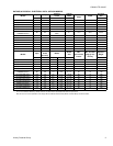
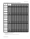
FILTER PERFORMANCE
The airflow capacity data published in the “Blower Perfor-
mance” table listed above represents blower performance
WITHOUT filters. To determine the approximate blower per-
formance of the system, apply the filter drop value for the fil-
ter being used or select an appropriate value from the “Filter
Performance” table shown below.
NOTE: The filter pressure drop values in the “Filter Perfor-
mance” table shown below are typical values for the type of
filter listed and should only be used as a guideline. Actual
pressure drop ratings for each filter type vary between filter
manufacturer.
NOTES:
1. Air velocity through throwaway type filters may not exceed 300
feet per minute. All velocities over this require the use of high
velocity filters.
2. Air flows above 1800 CFM require either return from two sides or
one side plus bottom.
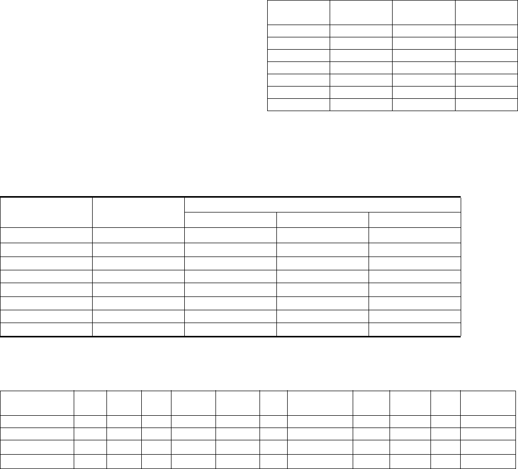
RECOMMENDED FILTER SIZES
CFM
Cabinet
Size
Side
(in)
Bottom
(in)
1200 A 16 x 25 14 x 25
1200 B 16 x 25 16 x 25
1600 B 16 x 25 16 x 25
1600 C 16 x 25 20 x 25
2000 C (2) 16 x 25 20 x 25
2200 C (2) 16 x 25 20 x 25
2000 D (2) 16 x 25 22 x 25
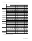
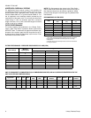
FILTER PERFORMANCE - PRESSURE DROP INCHES W.C. AND (KPA)
Airflow Range
Minimum
Opening Size
Filter Type
Disposable Washable Fiber Pleated
CFM
in
2
In W.C. In W.C. In W.C.
0 - 750 230 0.01 0.01 0.15
751 - 1000 330 0.05 0.05 0.20
1001 - 1250 330 0.10 0.10 0.20
1251 - 1500 330 0.10 0.10 0.25
1501 - 1750 380 0.15 0.14 0.30
1751 - 2000 380 0.19 0.18 0.30
2001 & Above 463 0.19 0.18 0.30
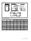
UNIT CLEARANCES TO COMBUSTIBLES (ALL DIMENSIONS IN INCHES, AND ALL SURFACES IDENTIFIED WITH THE
UNIT IN AN UPFLOW CONFIGURATION)
Application Top Front Rear
Left
Side
Right
Side
Flue
Floor/
Bottom
Closet Alcove Attic
Line
Contact
Upflow 1 6 0 0 3 6 Combustible Yes Yes Yes No
Upflow B-Vent 1 3 0 0 0 1 Combustible Yes Yes Yes No
Horizontal
1 6 0 0 3 6 Combustible No Yes Yes
Yes
1
Horizontal B-Vent
1 3 0 0 0 1 Combustible No Yes Yes
Yes
1
1. Line contact only permitted between lines formed by the intersection of the rear panel and side panel (top in horizontal postion) of the furance jacket
and building joists, studs or framing.