


035-19992-001 Rev. A (0404)
2 Unitary Products Group
7. NEVER…Store flammable materials of any kind near your fur-
nace. Gasoline, solvents, and other volatile liquids should be
stored only in approved containers outside your home. These
materials vaporize easily and are extremely dangerous.
8. NEVER
…Store cleaning materials near your furnace. Materials
such as bleaches, detergents, powdered cleansers, etc., can
cause corrosion of the heat exchangers.
9. NEVER
…Use the area around your furnace as a storage area for
items which could block the normal flow of air. This flow of air is
required for ventilation of the various furnace components.
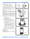
DESCRIPTION (50-125 MBH INPUT MODELS)
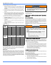
This furnace can be installed in the upflow, downflow, or horizontal left
or right position. Figure 2 shows a typical model in the downflow posi-
tion and Figure 1 shows a typical model in the upflow position. The fur-
nace may also lie on either side in a horizontal position. The furnace is
equipped with an induced-draft vent blower and atmospheric burners.
Combustion air is taken from the space or area in which the furnace is
installed and drawn into the burners through the louvers in the front
panel. Flue gas is drawn from the heat exchanger by the vent blower
and discharged through the flue pipe to the outside atmosphere.
This is a forced air furnace. The furnace circulating air blower draws
cool air from the house, passes it over the hot furnace heat exchanger
and circulates the warmed air through the ductwork to the house.
The furnace is equipped with the controls necessary for proper opera-
tion. The various components referred to in this manual and on the fur-
nace nameplate are identified in Figures 1, 2 & 3.
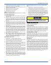
DESCRIPTION (150 MBH INPUT MODELS)
This furnace can be installed in the upflow or horizontal left or right posi-
tion. Figure 3 shows the 150 MBH input model. The furnace may also
lie on either side in a horizontal position. This furnace is not approved to
be installed in a downflow application. The furnace is equipped with an
induced-draft vent blower and atmospheric burners. Combustion air is
taken from the space or area in which the furnace is installed and drawn
into the burners through the louvers in the front panel. Flue gas is drawn
from the heat exchanger by the vent blower and discharged through the
flue pipe to the outside atmosphere.
This is a forced air furnace. The furnace circulating air blower draws
cool air from the house, passes it over the hot furnace heat exchanger
and circulates the warmed air through the ductwork to the house.
The furnace is equipped with the controls necessary for proper opera-
tion. The various components referred to in this manual and on the fur-
nace nameplate are identified in Figure 3.
FIRE OR EXPLOSION HAZARD
This furnace is designed and approved for use with Nat-
ural Gas and (LP) Propane Gas ONLY. DO NOT BURN
ANY LIQUID FUEL OR SOLID FUEL IN THIS FURNACE.
Burning any unapproved fuel will result in damage to the
furnace heat exchanger, which could result in Fire, Per-
sonal Injury, and/or Property Damage.
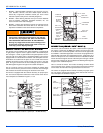
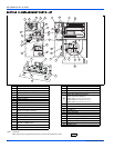
FIGURE 1: Component Locations - Upflow (50 - 125 MBH Models)
BLOWER
DOOR
SWITCH
ROLL-OUT
SWITCHES
BURNERS
HOT
SURFACE
IGNITOR
GAS
VALVE
PRESSURE
SWITCH
ROLL-OUT
SWITCH
DIRT
LEG
VENT
BLOWER
FURNACE
CONTROL
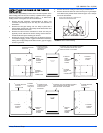
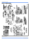
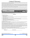
FIGURE 2: Component Locations - Downflow (50 - 125 MBH Models)
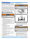
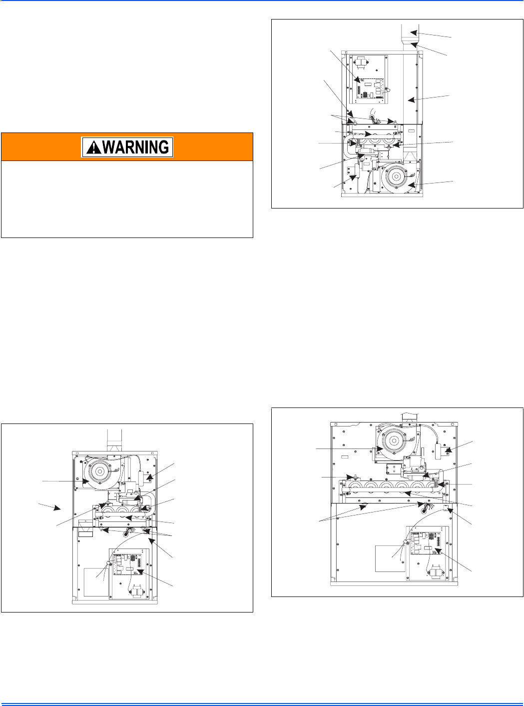
FIGURE 3: Component Locations - Upflow (150 MBH Models)
BLOWER
DOOR
SWITCH
ROLL-OUT
SWITCHES
BURNERS
HOT
SURFACE
IGNITOR
GAS
VALVE
PRESSURE
SWITCH
VENT
VENT PIPE
TRANSITION
3” DIAMETER
VENT PIPE
ROLL-OUT
SWITCH
VENT
BLOWER
FURNACE
CONTROL
BLOWER
DOOR
SWITCH
ROLL-OUT
SWITCHES
BURNERS
HOT
SURFACE
IGNITOR
GAS
VALVE
PRESSURE
SWITCH
ROLL-OUT
SWITCH
VENT
BLOWER
FURNACE
CONTROL