


127408-YIM-B-0606
24 Unitary Products Group
cabinet, if the unit has factory installed options. If field
installed accessories are being installed all parts necessary
for the installation comes in the accessory.
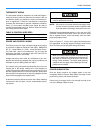
ECONOMIZER AND POWER EXHAUST SET POINT
ADJUSTMENTS AND INFORMATION
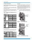
Remove the top rear access panel from the unit. Locate the
economizer control module, where the following adjustments
will be made.
MINIMUM POSITION ADJUSTMENT
• Check that the damper blades move smoothly without
binding; carefully turn the Minimum Position Adjust
screw (found on the damper control module) fully clock-
wise and then set the thermostat indoor fan switch to the
ON position and then OFF or energize and de-energize
terminals “R” to “G”.
• With the thermostat set to the indoor fan ON position or
terminals “R” to “G” energized, turn the Minimum Posi-
tion Adjusting screw (located on the damper control
module) counterclockwise until the desired minimum
damper position has been attained.
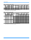
ENTHALPY SET POINT ADJUSTMENT
The enthalpy set point may now be set by selecting the
desired set point shown in the Enthalpy Set Point Adjustment
Figure 23. Adjust as follows:
• For a single enthalpy operation carefully turn the set
point adjusting screw (found on the damper control
module) to the "A", "B", "C" or "D" setting corresponding
to the lettered curve of the Enthalpy Set Point Adjust-
ment Figure 23.
• For a dual enthalpy operation, carefully turn the set point
adjusting screw fully clockwise past the "D" setting.
POWER EXHAUST DAMPER SET POINT (WITH OR WITH-
OUT POWER EXHAUST)
• With no power exhaust option, adjust the Exhaust Air
Adjustment Screw fully clockwise. This will allow 2nd
stage cooling to operate.
• With power exhaust option, each building pressurization
requirement will be different. The point at which the
power exhaust comes on is determined by the econo-
mizer damper position (Percent Open). The Exhaust Air
Adjustment Screw should be set at the Percent Open of
the economizer damper at which the power exhaust is
needed. It can be set from 0 to 100% damper open.
INDOOR AIR QUALITY AQ
Indoor Air Quality (indoor sensor input): Terminal AQ accepts
a +2 to +10 Vdc signal with respect to the (AQ1) terminal.
When the signal is below it's set point, the actuator is allowed
to modulate normally in accordance with the enthalpy and
mixed air sensor inputs. When the AQ signal exceeds it's set
point setting and there is no call for free cooling, the actuator
is proportionately modulated from the 2 to 10 Vdc signal, with
2 Vdc corresponding to full closed and 10 Vdc corresponding
to full open. When there is no call for free cooling, the damper
position is limited by the IAQ Max damper position setting.
When the signal exceeds it's set point (Demand Control Ven-
tilation Set Point) setting and there is a call for free cooling,
the actuator modulates from the minimum position to the full
open position based on the highest call from either the mixed
air sensor input or the AQ voltage input.
• Optional CO
2
Space Sensor Kit Part # 2AQ04700324
• Optional CO
2
Sensor Kit Part # 2AQ04700424
Replace the top rear access panel on the unit.
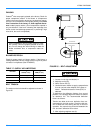
Extreme care must be exercised in turning all set
point, maximum and minimum damper positioning
adjustment screws to prevent twisting them off.