


035-13606-003 Rev. A (202)
Unitary Products Group 7
LOW VOLTAGE
Control wiring may vary depending upon the type of thermo-
stat and furnace being connected.
Low voltage wiring diagrams can be found with the furnace or
air conditioning blower package installation instructions.
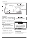
Pig-tail connector wires (2 blue or 1 blue, 1 brown) are pro-
vided from the low voltage pull-in coil on the contactor to a
section of the control box (See Figure 12). A “Fingered” bush-
ing is provided in the low voltage knockout hole. If 1/2" con-
duit is used for the low voltage wiring, the bushing is to be
removed.
1. Route the low voltage cable through the fingered bush-
ing in the low voltage junction box. See Figures 9, 10 &
11.
2. Using wire nuts, connect the low voltage wiring within the
low voltage box.
3. A minimum of 19 AWG wire must be used in connecting
the low voltage control wiring between the outdoor unit,
air handler thermostat, and outdoor thermostat. For
longer low voltage control wiring lengths, consult the
N.E.C.
Connect thermostat and control package wiring as shown in
Figure 12 and per the instructions packed with those pieces.
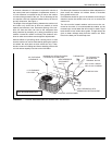
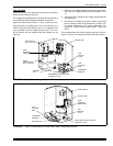
FIGURE 3 : Typical Condensing Unit Control Box (Start Components Shown)
START RELAY
(Not on all Models)
START
CAPACITOR
(Not on all Models)
DUAL
RUN/FAN
CAPACITOR
CONTACTOR
FAN
MOTOR
PLUG
“FINGERED”
BUSHING
LOW
VOLTAGE
BOX
REVERSIBLE HIGH VOLTAGE
CONDUIT PLATE
GROUND
LUG
FIGURE 4 : Typical Condensing Unit Control Box (Start Components Shown)
DUAL
RUN/FAN
CAPACITOR
GROUND LUG
CONTACTOR
FAN
MOTOR
PLUG
“FINGERED”
BUSHING
ADJUSTABLE HIGH VOLTAGE
CONDUIT PLATE
LOW
VOLTAGE
BOX
START RELAY