


035-13606-003 Rev. A (202)
6 Unitary Products Group
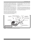
REFRIGERANT VALVE OPERATION
All models in this series have brass service valves. These
valves are not back seating. Opening or closing valve does
not close service port. Service ports have Schrader valves for
gauge connections. Use back-up wrench on valve body when
removing cap to open or close the valve. To open, insert hex
wrench into stem and back out counter clockwise until stem
just touches retaining ring.
Some units may have factory installed 1-1/8" ball valves. To
open the valve, remove the brass valve stem cap, located on
the side of the valve, with an adjustable wrench. Next, turn
the valve stem 1/4 turn CCW (away from unit).
All caps must be replaced to prevent leaks.
Replace valve cap finger tight, then tighten an additional 1/6
of a turn with a wrench, using a back-up wrench on the valve
body.
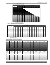
OIL TRAPPING
When the outdoor unit is above the indoor coil oil trapping is
necessary. Please refer to APPLICATION DATA, 690.01-
AD1V (1296) and worksheet 690.01-AD1.1V (791) “General
Piping Recommendations and Refrigerant Line length".
Check the system for correct charge after all components of
the system have been installed, connected and wired cor-
rectly.
Connect service gauges to low pressure port and discharge
service ports.
Allow unit to operate until system pressures and tempera-
tures have stabilized, making sure that the pressure and tem-
perature align with unit service data. If not, check system
charge and adjust if necessary.
ELECTRICAL WIRING
POWER SUPPLY
All wiring must comply with N.E.C. and local codes. See rat-
ing plate and product data sheet for volts, frequency, phase,
maximum fuse size and minimum branch circuit ampacity.
Refer to the wiring diagram inside the unit control box cover
before connecting to power supply.
1. The 208/230 volt single phase line voltage service wiring
for the outdoor unit must include a disconnect switch
located within sight of the outdoor unit.
2. Use the correct size fuse or circuit breaker as listed on
the unit rating plate and data sheet. If using nonmetallic-
sheathed cable (NM or NM-B) ampacities shall be that of
60° C conductors per N.E.C 336-26.
3. Wiring connections. - Two are provided in the control
box:
a. One for low voltage wiring.
b. One entrance for high voltage L1 and L2.
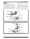
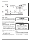
The adjustable High Voltage Conduit Plate is factory installed
for 1/2" conduit connections. For 3/4" conduit, remove the
screw holding the plate in place and adjust the location of the
holes. For 1" conduit, remove the conduit plate and discard.
Re-install screw to maintain the integrity of the unit structure,
regardless of the conduit being used. See Figures 9, 10 & 11.
4. Power connection to the unit is facilitated by screw termi-
nals, L1 and L2 on the outdoor unit contactor. See Fig-
ures 9, 10 & 11.
5. Ground the outdoor unit using the ground lug provided.
Unless the outdoor unit is grounded through proper wir-
ing to the service entrance ground, a suitable separate
ground should be provided at the outdoor unit.
6. Use copper conductors only.
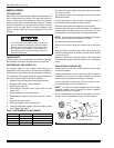
All outdoor units are shipped with the service
valves in the closed position. After installation of
the refrigerant and proper evacuation, make sure
that all valves are in the open position and that
the caps are securely tightened before turning
ON the electrical power to the outdoor unit.
If the valve stem is backed out beyond the retain-
ing ring, system pressure could force the stem
out of the valve body and possibly cause per-
sonal injury. In the event that the retaining ring is
missing do not attempt to open the valve.
To prevent electrical shock, open remote discon-
nect so electrical supply to outdoor unit is shut
off. Contactor does not open both sides of the
208/230 volt electrical circuit.
Casing or cabinet must be permanently grounded
in accordance with National Electric Code or
other applicable local codes.