


035-13606-003 Rev. A (202)
4 Unitary Products Group
INSTALLATION
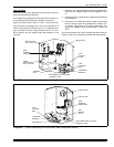
OUTDOOR UNIT
After the site has been selected, a solid base pad that will not
shift or settle should be provided. The base pad should not
come in contact with the foundation or side of the structure
because sound may be transmitted to the residence. The pad
should be located far enough away from the structure so the
outdoor unit is not closer than its minimum distances. See
Figure 1. Set the outdoor unit upon the pad with care to avoid
damage..
INDOOR UNITS
Install the indoor coil in the furnace or air handler according to
the installation instructions packed with each component.
REFRIGERANT LINE (SWEAT FIT)
The following steps are very important when setting up a
refrigeration system and need to be followed completely to
insure that a strong, flexible and leak tight system is obtained.
The installation of the copper refrigerant tubing must be done
with care to obtain reliable, trouble-free operation.
1. Selection of proper refrigerant tubing grade and size.
2. Refrigerant line routing, cutting and fitting.
3. Insulating the vapor line.
4. Connecting the refrigerant lines to the indoor coil and
outdoor unit.
5. Proper preparation of joint connections.
6. Reassembling, cleaning and brazing the joint connec-
tions.
7. Pressure leak test all joints.
8. Evacuate refrigerant lines and indoor coil.
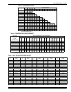
9. Charging refrigeration system (If the line length is other
than 15 feet). See Table 2.
Use only ACR grade copper tubing and keep ends sealed
until joints are made.
The correct diameters of the refrigerant lines are listed in the
Tabular Data Sheet.
For best performance, select routing of refrigerant lines for
minimum distance and fewest number of bends.
Determine the path that the refrigerant lines will follow.
Starting at either the indoor coil or the outdoor unit refrigerant
line connections, carefully measure, cut, de-burr and fit cop-
per refrigerant lines along the path previously determined.
NOTE: If it is necessary for bends to be formed in the vapor
line, the radius should not be less than 12 inches.
Cut ends of the copper tubing square.
Remove all burrs from tubing with a reamer, file or de-burring
tool.
When the indoor coil is above the outdoor unit, the vapor line
should be sloped toward the outdoor unit with a fall of at least
1/4 inch per 5 feet.
When the outdoor unit is above the indoor coil the horizontal
runs should be sloped toward the outdoor unit as described
above.
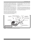
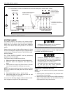
INSULATION OF VAPOR LINE
Insulate vapor line with 3/8" (or that required by local code)
closed cell insulation.
Slide tubing insulation onto the vapor line so that it is covered
completely from the indoor coil to the outdoor unit. Be sure
that the tubing is capped before sliding on insulation.
It is not necessary to insulate the liquid line, unless it is sub-
ject to excess heat in an uninsulated area.
NOTE: In areas of extreme temperatures and humidity,
additional insulation may be required to prevent excessive
condensation and loss of capacity.
Do not insulate liquid line and vapor line together. Liquid line
should not be in contact with the vapor line. See Figure 2.
Do not remove the protective caps or plugs from
the unit refrigerant connections until the refriger-
ant lines are run and ready for final connection. If
this procedure is not observed, dirt and other par-
ticles will get into the system and plug various ori-
fices and small tubes.
Table 2: REFRIGERANT LINE CHARGE
LIQUID OD VAPOR OD R-22 CHARGE, OZ/FT
3/8" 5/8" 0.66
3/8" 3/4" 0.68
3/8" 7/8" 0.70
3/8" 1-1/8" 0.76
FIGURE 2 : INSULATION OF VAPOR LINE
Liquid
Line
Incorrect
Correct
Tape
Sheet Metal Hanger
Insulated Vapor Line