


035-18843-000-A-0402
6 UnitaryProductsGroup
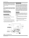
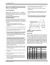
To install the filters, remove the filter access panel
located to the left of the condensate drain connection
asshowninFigure5.
NOTE: Filters must be installed with “Air Flow” arrows
pointing inward -- toward the indoor coil. In the
event the spacers in the filter section are
removed, they must be reinstalled in their origi-
nal position.
Slide filters all the way into the filter racks provided.
When more than one filter in a filter rack is required,
they must butt each other when sliding into position.
Replace the filter access panel.
BLOWER ASSEMBLY
Even with good filters properly in place, blower wheels
and motors will become dust laden after many months
of operation. The entire blower assembly should be
inspected annually. If the motor and wheel are heavily
coated with dust, they can be brushed and cleaned
with a vacuum cleaner.
These units are supplied with blower shaft bearings
that do not require maintenance but may be relubri-
cated if desired. Every three years, using a low pres-
sure grease gun, pump grease into the bearing grease
fitting until grease just begins to show at the seals. Do
not over lubricate. Use any lithium base grease recom-
mended for ball bearing service.
MOTORS
Outdoor fan motors are permanently lubricated and
require no maintenance.
Ventor motor is factory lubricated for an estimated 10
year life.
Indoor Blower Motor and Drive - The indoor blower
motor features ball bearings that do not require peri-
odic lubrication. Periodic lubrication of the motor and
bearings can extend the life of components but is
optional.
If desired, every three years, using a low pressure
grease gun, pump grease into the bearing grease fit-
ting until grease just begins to show at the seals. Do
not over lubricate. Use any lithium base grease recom-
mended for ball bearing service.
Perform all maintenance operations on the blower
motor with electric power disconnected from the unit.
Do not attempt to lubricate bearings with the unit in
operation.
FIGURE 5: END VIEW LESS FILTER ACCESS
PANEL
(2) 14" X 20"
FILTERS
(1) 14" X 25"
FILTERS
INDOOR COIL
CONDENSATE
DRAIN
CONNECTION
INDOOR COIL
INDOOR COIL
CONDENSATE
DRAIN
CONNECTION
CONDENSATE
DRAIN
CONNECTION
3 - 6 TON UNIT
15 & 20 TON
STANDARD & HIGH
EFFICIENCY UNITS
15, 17.5, 20, 25 TON ULTRA-HIGH EFFICIENCY UNITS
(4) 16" X 20"
FILTERS
(4) 16" X 25"
FILTERS
(6) 12" X 24"
FILTERS
(6) 12" X 24"
FILTERS
15 TON
(2) 18" X 24"
20 TON
20 TON
15 TON
(3) 18" X 24"
FILTERS
FILTERS
25 TON STANDARD EFFICIENCY