


035-18843-000-A-0402
Unitary Products Group 5
mary air shutters to give a distinct, sharp blue flame as
explained under BURNER AIR SHUTTER ADJUST-
MENT. If it is not possible to adjust for the proper flame,
the burners may need cleaning.
CLEANING BURNERS
Remove them from the furnace as explained in
BURNER INSTRUCTIONS section in the Unit Installa-
tion Instructions. Clean burners with wire brush and
vacuum as needed.
CLEANING FLUE PASSAGES AND
HEATING ELEMENTS
With proper combustion adjustment, the heating ele-
ment of a gas fired furnace will seldom need cleaning.
If the element should become sooted, it can be cleaned
as follows:
1. Remove the burner assembly as outlined in
“BURNER INSTRUCTIONS” of the unit installation
instructions.
2. Remove the unit roof from over the gas heat section.
3. Remove the top plate and the top draft blower wheel
from the upper draft blower housing.
4. Remove the screws holding the top of the flue collec-
tor box. Carefully remove the top of the flue collector
box without ripping the adjacent insulation. Then
remove the center divider plate separating the upper
and lower flue boxes.
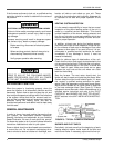
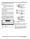
5. On the inside of the flue collector box, remove the
flue baffles from the tube interiors. Note the last
bend of the baffle fits tightly against the tube forcing
the end of the baffle to lock into the tube collar. This
collar is formed when the tube is expanded into the
end sheet. To remove, move the end of the baffle
toward the center of the tube releasing the end of the
baffle from the tube collar, then pull straight out of
the tube. Refer to Figure 4.
6. Using a wire brush on a flexible wand, brush out the
inside of each heat exchanger from the burner inlet
and flue outlet ends.
7. Brush out the inside of the flue collector box and the
flue baffles.
8. Run the wire brush down the vent hoods from the
flue collector end.
9. If soot build-up is particularly bad, remove the vent
motor and clean the wheel and housings. Run the
wire brush down the flue extensions at the outlet of
the vent housings.
10.After brushing is complete, blow all brushed areas
with air or nitrogen. Vacuum as needed.
11.Replace parts in the order they were removed in
Steps 1 thru 5.
12.When replacing the center and top of the flue collec-
tor box, be careful not to tear the adjoining insula-
tion.
13.Ensure that all seams on the vent side of the com-
bustion system are air tight. Apply a high tempera-
ture (+500°F) sealing compound where needed.
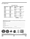
AIR FILTERS
Units up through 125 MBH input (3-6 Ton) are shipped
with 1" throwaway type air filters. All other units contain
2" filters. The filter racks on 3-6 ton units will receive 1"
or 2" filters. Filters can also be installed in the building
at a suitable return air location if an economizer or out-
side air accessory is not used. Filters must always be
used. They should be inspected once a month and
thoroughly cleaned or replaced if it appears they are
beginning to accumulate excessive dirt. Filter sizes and
quantities are shown in the following table.
FIGURE 4: TYPICAL FLUE BAFFLE
INSTALLATION
THROW
AWAY
FILTER
SIZES
(Inches)
QUANTITY PER UNIT (Nom, Tons)
3-6
TON
15
TON
STD
&
HIGH
EFF.
20
TON
STD
&
HIGH
EFF.
25 TON STD
EFFICIENCY
15 - 25 TON ULTRA
HIGH EFFICIENCY
14x20 2 ~ ~ ~ ~
14x25 1 ~ ~ ~ ~
12 x 24 ~ ~ ~ 12 12
16x 20 ~ ~ 4 ~ ~
16x25 ~ ~ 4 ~ ~
18x24 ~ 5 ~ ~ ~