August 2004
INSTALLATION INSTRUCTIONS
Page 46
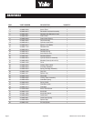
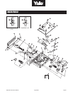
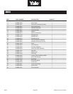
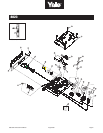
8800 Series Parts & Service Manual
Yale
®
Mortise Locks
8800 Series (Knob, FL and SL Trim)
NOTES
The following is a step by step approach to installing a mortise lock and trim to both wood and steel doors.
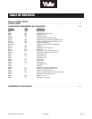
1) Determine Hand of Door 7) Install Strike
2) Mark Position and Door Template 8) Sectional Trim
3) Drill Holes in Door 9) Escutcheon Plate Trim (Thru-bolted)
4) Mark Frame for Strike and Mortise Cavities 10) Escutcheon Plate Trim (Surface Mounted)
5) Drill Mortise Cavities in Door and Frame 11) Single Operational Trim (Sectional and Escutcheon)
6) Install Lock (Wood or H.M Door) 12) Check Operation of Lock
1) DETERMINE HAND OF DOOR
a. Face the door from the outside to determine its hand. Please note the outside is either the key side of an entrance
door or the corridor side of a room door. The outside of a single communicating door is the side opposing the hinges.
The outside of twin communicating doors is the space between the doors.
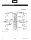
2) MARK POSITION AND DOOR TEMPLATE
a. Draw a horizontal centerline for the lock on both sides of door at desired height above finished floor line. Standard
height for horizontal centerline is 39-15/16” above finished floor.
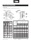
b. Select template by comparing handing of door to Fig. 4, 5 and 6.
c. Compare the lock function number being installed with (See Fig. 3) to determine the holes to be marked.
d. Position the installation template on the door so that the horizontal centerline lines up with the horizontal line on the
door. Mark the holes to be drilled using a scribe, center punch, or nail on the inside and outside of door. To avoid
shifting of the template, it may be taped to the door during this step.
e. On the edge of the door mark the holes to be drilled for the mortise cavity and armor front attaching screw holes.
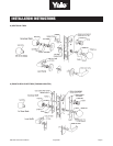
3) DRILL HOLES IN DOOR
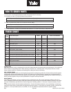
a. Bore marked lock trim holes (steps 2d and 2e). To avoid splintering wood, bore thru holes from both sides of door. For
hole sizes refer to hole chart. Note: Hole “A” diameter is different for FL & SL Applications.
4) MARK FRAME FOR STRIKE MORTISE CAVITIES
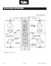
a. Mark vertical position of strike on jamb using the reference centerline on installation template (see Fig. 4, 5 or 6).
Mark location of strike lip. (FIRST DETERMINE IF SILENCERS ARE TO BE USED) To locate horizontal centerline of
strike, take half the door thickness PLUS the thickness of silencer (if used). Use this dimension to locate the strike
centerline from the doorstop. (See Fig. 1.)
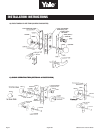
5) DRILL MORTISE CAVITIES IN DOOR AND FRAME
a. Mortise door edge for lock body. Drill pilot holes for attaching screws.
b. Slide lock body into cavity with armor front attached. Align armor front with top mark. Use lock front as template. Mark outline.
c. Mortise door edge for lock front (7/32”) deep.
d. Mortise jamb for strike (3/32” deep). Be sure to mortise 1” (25mm) deep to accommodate lock bolts or strike box
if used. (See Fig. 1)
Note: Before installing lock, prepare door trim per sections 8, 9,10 or 11.
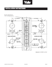
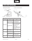
6) INSTALL LOCK (WOOD OR H.M. DOOR)
a. Remove armor front.
b. If necessary, change handing of lock by following instructions on lock. Do this to match your door hand.
c. Insert lock body into cavity in door and secure base front with two #12 combination attaching screws. Make sure lock
is positioned in cutout properly. (See Fig. 3.) Note: Installation may require leaving #12 combination screws loose until
trim and cylinder are assembled in lock body.