


1. Check that there are no buried pipes or
cables (eg. Electricity, gas, water) behind
the switch location (in the wall or above
the ceiling).
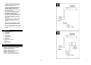
2. Lay in the cable from the isolating switch to
the fan location via the on/off switch (see Fig.
E1. For change over switch (COS) see Fig.
E2.
3. Lay in the cable from the isolating switch to
the point of connection to the mains supply.
WARNING: DO NOT MAKE ANY
CONNECTIONS TO THE ELECTRICITY
SUPPLY AT THIS STAGE.
4. Install the isolating switch and the on/off
switch, see Fig. E1. For change over switch
(COS) see Fig. E2.
5. Make all connections within the isolating
switch, on/off switch and change over switch
(COS) if required.
Note: When installed in a bathroom all switches
must be of a pull cord type and must be situated
so that they can not be touched by persons
making use of the bath or shower.
Permanently connected to the supply and a
remote switch operation. Wire directly to the
supply through an approved 10A wall mounted
surface switch with at least 3mm clearance
between contacts.
If working above ground level, appropriate safety
precautions must be observed.
WARNING: EYE PROTECTION MUST BE WORN
DURING ALL DRILLING AND CHISELLING
OPERATIONS.
1. Check there are no buried pipes or cables
in a wall or obstructions on the outside
(eg. Electricity, gas, water).
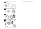
2. Ensure that the centre of the hole is located
at least 145mm from the edges of the wall,
see Fig. A.
3. Mark on the centre of the duct hole.
4. Use this centre to draw a circle to suit the wall
duct (203mm diameter for a WK6/300 or
WK6/450).
5a. Use as directed by the core drill
manufacturer.
5b. Drill a centre hole right through the wall.
6. Cut the hole. Do not cut right through the wall
(the recommended method is to drill a series
of holes, close together, around the edge of
the cutting line and remove the brick between
the holes with a chisel).
7. Go outside and cut a hole in the outer wall,
repeating the process described above.
8. Fit the ducting. Ensuring that the duct slopes
down away from the fan to allow drainage of
any incoming rain water to the outside.
9. Make good the hole. Allow for the mortar to
set before continuing with the installation.
Obtain a ready cut pane with a correctly located hole
184mm diameter, see Fig. A.
1. For window mounting, use the two short
ladder strips supplied with the fan.
For wall mounting, use the longer ladder
strips supplied with the wall kit WK6/300 or
WK6/450.
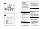
2. Secure the two ladder strips to the outer grille
by positioning them over the hook moulding
and snapping them into position.
3. Ensure after fitting the hook moulding that the
gasket is in the correct position, see Fig. B.
4. Insert the two screw covers in the two fixing
holes in the outer grille.
If working above ground level, appropriate safety
precautions must be observed.
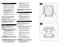
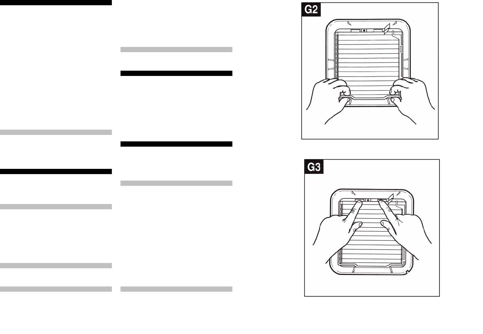
Remove the back draught shutter/grille assembly by
pressing the release catches located on the sides of
the unit with a 6mm screwdriver or a coin, whilst
pulling the grille forward.
1. Hold up the outer grille to the outside wall or
window so that the hole in the outer grille is
aligned with the hole in the wall or window.
2a. If wiring from the rear, remove the fan’s
terminal cover and rear entry knockout. Feed
the cable through the rear cable entry.
2b. If wiring from above, remove the fan’s
terminal cover and feed the cable through the
top cable entry.
3. Hold the fan assembly to the inside of the wall
or window and guide the ladder strips from
the outer grille through the slots in the fan
assembly.
4. Insert the slotted screws into the pockets
around the ladder strip slots.
5. Tighten the screws carefully to make a good
seal, do not over tighten the screws.
6. Trim the ladder strips back to the required
length, if necessary remove any sharp edges.
1. Hold the outer grille up to the outside of the
wall so that the hole in the outer grille is
aligned with the hole in the wall.
2. Mark the positions of the fixing holes in the
top right and bottom left corners.
Installing the switches and cables
For Australia only
Preparing the hole
If installing in a wall
If core drill equipment is available
If core drill equipment is not available
If installing in a window
Preparing the fan for installation
Mounting the fan in the hole, Fig. C.
If installing with ladder strips
If using screw fixings
8
5