4
The next step is to determine which Waterpad version and
keypad button icons are required to perform this job, as follows:
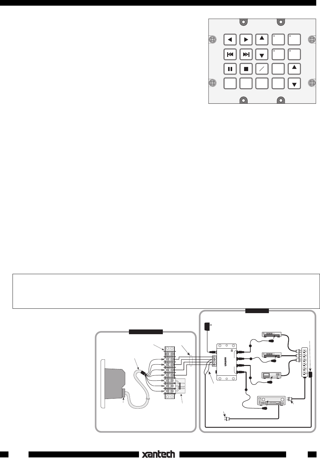
1. Since there are 4 sources, 4 banks will be required. We will
need the WPK-4 Waterpad version as shown in Fig. 1.
PLEASE NOTE:
All four versions of the Waterpad appear the
same before the button Icons are applied. That is, all the
buttons in the right 2 columns have a small dark circle in their
upper left corner where LEDs are located for bank (source)
indicators. These LEDs are programmed at the factory to
operate depending on the Waterpad version you ordered.
That is, on the WPK-1 none operate, on the WPK-4, the upper
4 operate, on the WPK-6 the upper 6 operate and on the
WPK-8, all 8 operate. On the versions where the LEDs do not
operate, the buttons work as normal function keys. When you apply function icons to them, the
unused LEDs are covered up as in Fig. 2.
2. The next step is to determine exactly what button icons are required to identify the source and control
functions needed.
3. We begin this process by assigning the source buttons first; CD1, TUNER, CD2 and TAPE. See Fig.
2. We do this by using Dragon Drop IR™. You may also pencil out your button designations on the
blank Waterpad illustrations at the end of this manual prior to using Dragon Drop if you wish.
4. Next, we assign the function control buttons based on the list of functions given in the client
specification, in the same manner.
5. Now that all the buttons have been assigned (as shown in Fig. 2), it is necessary to memorize the IR
commands and do the programming. Refer to the Dragon Drop IR™ Installation and Programming
Instructions for this process.
NOTE: In this example, the button assignments are placed in what is considered an ergonomically
pleasing arrangement. You may, however, assign the buttons in any arrangement you wish, to best
fit taste and application. The only exception to this is the 4 source buttons. These are permanently
assigned to the upper positions in the two right columns.
PROGRAMMING THE WATERPAD
TM
- The Waterpad series was designed to be programmed
entirely using the Dragon Drop IR
TM
system with software DD3 ver. 3.0 and higher.
It cannot be
programmed directly!
Refer to the Dragon Drop IR
TM
DD4 Installation and Programming
Instructions for details.
Up to this point, the Waterpad exists only as a virtual
keypad in Dragon Drop-IR™.
For the final steps, we would
proceed as follows:
6. All commands are
tested, while still in
Dragon Drop-IR™, to
see that they actually op-
erate all system func-
tions.
7. The programmed data
is then transferred to the
"real" Waterpad, using
Dragon Drop-IR™.
Fig. 2 Typical 4-Source Button Assignment
CD 1
TAPE
A/B
VOL
VOL
CD 2
TUNER
TNR
TNR
OFF
MUTE
DISC
+
DISC
---
AM
FM
Fig. 3 Typical 4-Source Waterpad Controlled System
WPK1
TX RX COM
+12V
(red)
STATUS
(green)
COMMON
(orange)
RX
(blue)
TX
(brown)
Six foot, 7-Conductor Cable
(End of cable is not
waterproof-see text).
Waterproof
Cable Bushing
COM PORT Adapter PCB
(included in Dragon Drop IR
for program transfers)
8-Terminal Block
(place in a dry location)
THE WATERPAD™
(side view)
AM/FM Receiver
To 120 V AC
(unswitched)
781RG
Power Supply
789-44
Connecting Block
4-Conductor
Inter-room Cable
(Unshielded OK)
White Striped Side ("+")
(Power ON/OFF Status
Voltage)
786-00
Power Supply
(12V)
Plug into
Switched AC Outlet
on AM/FM Receiver
REMOTE LOCATION
MAIN ROOM
–
+
283M
Blink-IR™
283M
Blink-IR™
Mouse Emitter
AC
Power
Strip
Power Cord for
AM/FM Receiver.
Plug into an
Unswitched
AC Outlet
Cassette DecK
CD Changer 2
283M
Blink-IR™
283M
Blink-IR™
CD Changer 1
GND
(black)
IR OUT
(white)
12VDC
+12 VDC
GND
STAT US
IR IN
EMITTERS
IR
RCVR
789-44
CONNECTING BLOCK
®


