20 Dealer Service
MAN0661 (8/10/2007)
DEALER SERVICE
The information in this section is written for dealer ser-
vice personnel. The repair described here requires
special skills and tools. If your shop is not properly
equipped or your mechanics are not properly trained in
this type of repair, you may be time and money ahead
to replace complete assemblies.
NEVER GO UNDERNEATH EQUIPMENT. Never
place any part of the body underneath equipment
or between moveable parts even when the engine
has been turned off. Hydraulic system leak-down,
hydraulic system failures, mechanical failures, or
movement of control levers can cause equipment
to drop or rotate unexpectedly and cause severe
injury or death.
• Service work does not require going under-
neath.
• Read Operator's Manual for service instruc-
tions or have service performed by a qualified
dealer.
Do not allow bystanders in the area when oper-
ating, attaching, removing, assembling, or servic-
ing equipment.
Do not modify or alter or permit anyone else to
modify or alter the equipment or any of its compo-
nents in any way.
Do not disconnect hydraulic lines until machine
is securely blocked or placed in lowest position
and system pressure is released by operating
valve levers.
Make sure attachment is properly secured,
adjusted, and in good operating condition.
Make sure all safety decals are installed.
Replace if damaged. (See Safety Decals section for
location.)
Make sure shields and guards are properly
installed and in good condition. Replace if damaged.
Always wear relatively tight and belted clothing
to avoid getting caught in moving parts. Wear
sturdy, rough-soled work shoes and protective
equipment for eyes, hair, hands, hearing, and head;
and respirator or filter mask where appropriate.
REPLACE BRUSH SECTIONS
1. Remove motor mount screws. Retain hardware for
reinstallation. Remove motor mount.
2. Remove bearing mounting plate screws from side.
Retain hardware for reinstallation.
3. Remove the side flaps. Retain hardware for
reinstallation.
4. Lift sweeper body leaving core on ground.
5. Remove the bearing mounting plate and section
retainer plate. Retain hardware for reinstallation.
6. Remove old sections.
Install New Sections
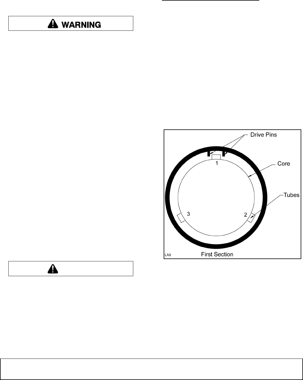
1. Number the tubes on the core as 1, 2 and 3. See
Figure 13.
Figure 13. Number Tubes
2. Slide the first section onto the core with the drive
pins on either side of tube 1. Make sure that the
drive pins angle upward (Figure 13).
CAUTION


