


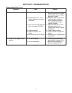
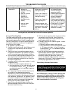

4. With test resistor
connected (per item H2)
and TD114 locally
connected (per item H3)
turn TD114 selector dial
through entire modulating
range. Observe D.C.
voltage across modulator
terminals.
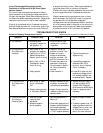
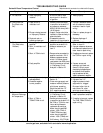
1. Inlet Air Sensor changes
1° or each 3.5°, 5° or 8°
outside temperature change
from 60° (predetermined -
turndown varies with
model used).
2. Check wiring diagram for
heater.
3. Sensed temperature
(thermometer next to
TS114) does not correspond
to TD114 setting.
4. Sensed temperature (thermo-
meter next to TS114) does
not represent average
discharge air temperature.
5. Remove Override
Thermostat lead from
terminal 2 of TD114.
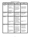
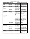
1. Measure resistance across
modulator terminals with
red lead wires disconnected.
2. Inspect wiring.
1. Check “Override Tempera-
ture Selector” of TD114.
2. Check for high fire (Maxitrol
manifold pressure specified
for heater).
1. Read voltage across auto
valve terminals. If 24V AC,
valve is faulty.
2. Read voltage across
terminals 5 & 6. If 24V AC,
check for open circuit to
automatic valve.
4. Faulty Amplifier or
erratic voltage supply.
1. Inlet Air sensor is used.
2. Incorrect wiring.
3. System out of
calibration.
4. Improper TS114
location.
5. Room Override
Thermostat circuit
closed.
1. Short circuit in
modulator coil.
2. Short circuit
between amplifier
and modulator valve.
1. Override Temperature
setting is too low.
2. Burner capacity may be
insufficient.
1. Faulty automatic
control valve.
2. Open wire to automatic
valve.
13
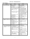
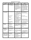
Symptom Possible Cause
Field Test
Remedy
H. continued
I. Incorrect Discharge
Air Temperature
J. Burned out
Transformer.
K. Discharge Air
Temperature too
low when TS115
is operative.
L. Automatic Control
Valve will not open
despite full range of
modulating voltage
at terminals 3 & 4.
4. If erratic or unstable D.C.
voltages are obtained
throughout the modulating
range, the amplifier may be
assumed faulty. Replace. If
erratic operation is noted
only over a small range of
2 or 3 volts, the voltage
sources may contain surges.
Consult factory for other
solutions.
1. Sensed temperature will
vary from TD114 dial
settings. This is intentional.
2. Correct wiring.
3. See calibration procedure.
4. Move TS114 to location
where average representative
temperature can be sensed.
5. TD114 dial setting, then check
thermostat setting and/or
check wiring for shorts.
1. Replace modulator head if
less than 40 ohms.
2. Correct wiring if short
is found.
1. Reset to correct temperature.
2. If on high fire, control can
do no more. Heater unable
to furnish additional heat to
raise temperature.
1. Replace automatic control
valve.
2. Correct wiring.
TROUBLESHOOTING GUIDE
Series 14 Discharge Temperature Control continued Reproduced with permission from Maxitrol® Company