


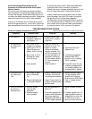

12
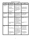
Symptom Possible Cause
Field Test
Remedy
E. Continuous High
Fire (Electronics
Problem).
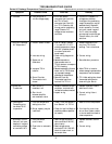
F. Continuous High
Fire (Electronics
OK).
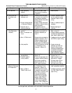
G. Incorrect
Maximum Fire.
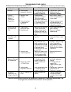
H. Erratic or Pulsating
Flame
1. Short circuit in TD114
Remote Temperature
Selector circuit or wiring.
2. Open circuit in
TS114/TS1007
Discharge or Inlet Air
Sensor circuit or wiring.
3. Jumper not connected
across amplifier
terminals 2 & 3.
1. Foreign object holding
valve open.
2. Plunger jammed.
1. Inlet pressure too low.
2. Incorrect outlet pressure
adjustment of Pressure
Regulator.
1. Hunting
2. Erratic air patterns or
improper TS114 location.
3. Wiring is run next to
high voltage switching
circuits causing induced
voltages.
1. Inspect for shorts at or
between Amplifier terminals
1 & 2 or TD114 terminals
1 & 3.
2. Check TS114/TS1007 for
open internal circuit.
Connect test resistor as
described in Preliminary
Circuit Analysis. Follow
procedure outlined.
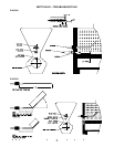
3. Inspect.
1. Remove bottom plate and
inspect valve and seat.
2. Inspect. Plunger should be
smooth and clean and
operate freely in solenoid
sleeve.
1. Read pressure at inlet to
modulating valve using a
manometer with unit
operating at full fire.
Pressure should be equal
to the sum of outlet pres-
sure setting plus pressure
drop of the valve.
2. Read manifold pressure
using manometer and
compare with the pressure
stated on the specification
plate.
1. Adjust sensitivity control
counter-clockwise.
2. Connect test resistor
as described in Preliminary
Circuit Analysis.Turn
TD114 selector dial so
heater goes through its
entire modulating range.
3. Temporarily wire each
TD114,TS114 and MR212
externally and observe
heater/equipment
operation.
1. Correct wiring if shorts exist.
2. If modulating voltages are
obtained, check TS114/
TS1007 for open circuits.
Replace TS114/TS1007.
3. Correct the wiring.
1. Clean seat. Clean valve
or replace if necessary.
2. Clean or, if necessary,
replace plunger
1. Increase inlet pressure if
possible.
2. See valve adjustments in
Section IX.
1. If flame stabilizes, adjust
sensitivity control to
maintain an even flame.
2. If the flame is steady
throughout the entire
modulating range, the
TS114 must be moved.
3. If smooth operation
results, isolate affected
wiring from source of
induced voltage.
TROUBLESHOOTING GUIDE
Series 14 Discharge Temperature Control continued Reproduced with permission from Maxitrol® Company