


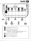
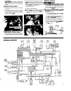
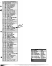
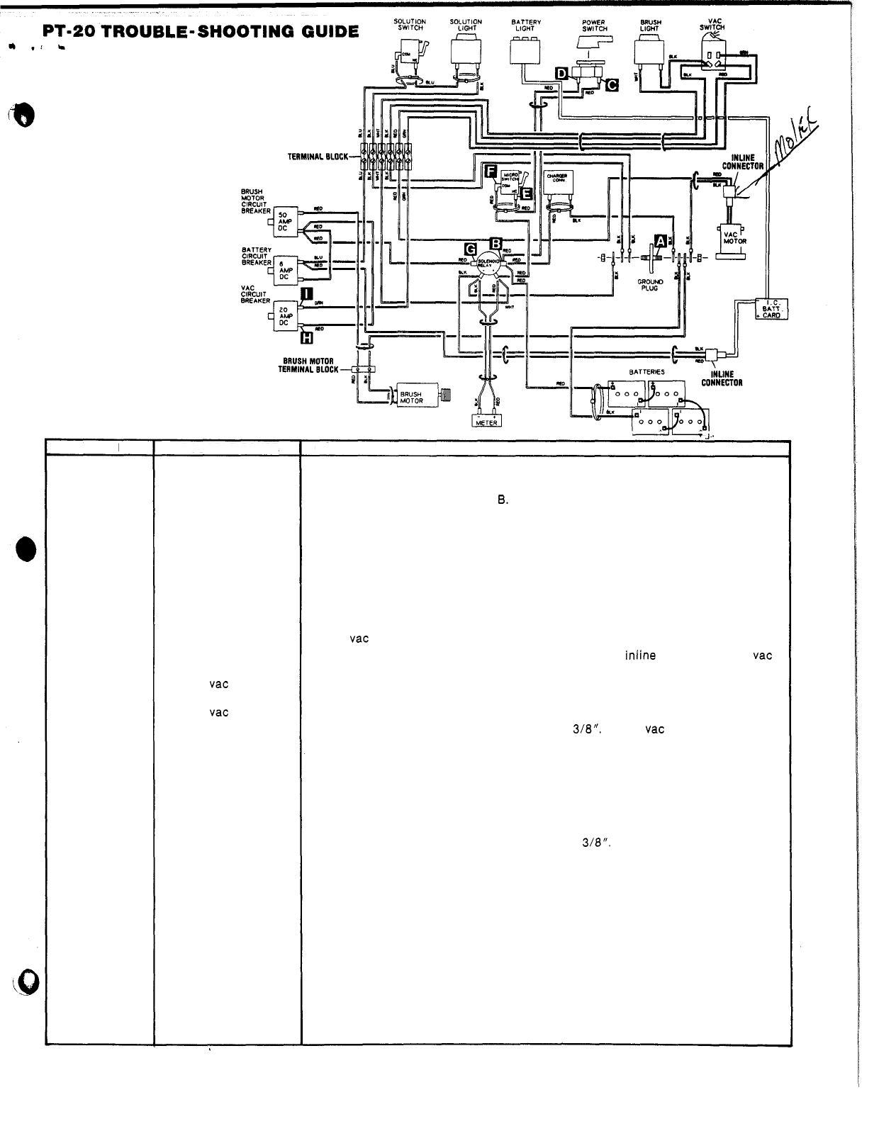
PROBLEM
No
power.
Vacuum motor
does not run.
Brush motor
does
not
run.
Solution light
does
not work.
Battery charge
level Indicator
lights.
PROBABLE CAUSE
Circuit breaker tripped.
Battery cables corroded
at battery terminals.
Faulty main switch.
Faulty safety override
micro switch.
Faulty solenoid.
Circuit breaker tripped.
Loose connections.
Faulty
vac circuit
breaker.
Faulty
vac switch.
Motor brushes worn.
Circuit breaker tripped.
Loose connection.
Faulty solenoid.
Faulty drive motor.
Faulty circuit breaker.
Loose connections.
Faulty solution light.
Light stay on with
solution lever in
“OFF” position.
No
light are on with
main switch on.
Loose connections.
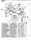
I
7
J.
CORRECTIVE ACTION
Reset brush motor circuit breaker
(50
amp).
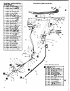
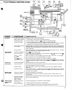
1. Clean battery cable clamps and battery terminals.
2. Check voltage at points A and
B.
Voltage should be 22/26 VDC.
1.
Check voltage at points A and C. Voltage should be 22/26 VDC.
2. Turn main switch on and check voltage at points A and D. Voltage should be
With main switch
“ON”
check voltage at points A and
E
and
A
and F. Voltage should
be 22/26 VDC.
If
no voltage at A and F remove leads and check micro switch for
continuity. Should be continuity
in
normal position and no continuity when switch
lever is activated.
With main switch on (solenoid energized) check voltage at points
A
and
G
-
voltage
should be 22/26 VDC.
If
no voltage replace solenoid.
Reset
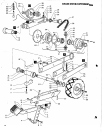
vac motor circuit breaker.
Check motor lead connections at terminal block and
inline connector near vac
motor. Keep all connections tight.
With main switch on check voltage at points A and H and A and
I.
If
no voltage,
check continuity of circuit breaker. Replace as needed.
Remove leads and check switch for continuity. Replace as needed.
Check motor brushes. Replace when worn to
W8“.
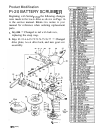
Check vac motor by securing
motor and applying
24
VDC
to
motor leads.
No
load amp draw of motor should be
15
amp.
Reset
(50
amp) brush motor circuit breaker.
Check motor leads at terminal block connection (located under right hand lower
side panel) tighten set screws as needed.
With main switch on check ouput voltage at points A and
G.
Voltage should be
22/26 VDC.
Check motor brushes
-
replace when worn to 3/8“. With batteries fully charged
and motor secured, apply battery voltage direct to motor.
No
load amp draw
of
motor
should be 12 to 13 amps.
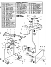
Reset (6 amp) battery circuit breaker.
Check for loose electrical connections at terminal block, solution switch, and
solution light.
Remove light and apply direct battery voltage (24 VDC)
to
light. Replace light as needed.
Adjust solution light switch.
22/26 VDC.
If
no voltage remove leads and check switch for continuity,
Check (6 amp) battery circuit breaker. Reset
if
tripped.
1.
Check electrical connections at circuit breaker.
2. Check voltage at inline connector at PC Board. Should be 22/26 VDC.
17