


OPERATION USING ADJUSTABLE DIAL SWITCH
To adjust desired temperature and program the timer.
Select the desired temperature by turning Adjustable Dial
Switch when using the unit in cooling or heating function.
The desired temperature range is from 61
o
F-88
o
F (16
o
C-
31
o
C). The LED flashes to display the desired
temperature during the setting, it displays the room
temperature after 5 seconds, .
Press Timer On/Off button, turn adjustable dial switch to
change the clock to the desired time for the unit being
turned on or off.
1. Remove the cover from the back of the remote control.
2. Insert two AAA dry-cell batteries (batteries included)
3. Insert the power plug into an outlet.
4. Always point the remote control signal transmitter
toward the unit when operating.
5. Make sure that the signal path is not obstructed.
6. The maximum distance at which signals can be
received is 26.24 feet.
7. Remove the batteries if the unit is not going to be used
for an extended period of time.
NOTE:
1. Do not abuse the remote control.
2. Do not place the remote control in a location that is
exposed to direct sunlight or next to a heating unit or
other heat source.
3. Do not use rechargeable batteries because they
differ from standard dry cell batteries in shape,
dimension and performance.
4. Be sure to replace the batteries with two new
batteries of the same type.
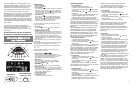
REMOTE CONTROL FUNCTIONS
1. ON/OFF-
Starts or Stops the Unit
2. WARM
Adjust to desired warm temperature.
3. COOL
Adjust to desired cool temperature.
4. MODE
Select the functions of the unit for: Fan Mode,
Air Conditioning Mode, Heating Mode,
Dehumidifying Mode and Auto Mode
5. TEMP./%
To display temperature or humidity on both Main LED and
LED. Hold the button more than 3 seconds, to convert the
temperature display from Fahrenheit (
o
F) to Celsius (
o
C)
and vice versa. Press the button for less 3 seconds to view
the humidity.
6. FAN
Select the fan speed desire: High, Medium and Low
The fan speed can be visually distinguished by the speed
of the digital air segments progressing out from the wind
mill fan image on the Main LED display.
7. SWING
To start swinging air louvers horizontally by press SWING
Button once. At the moment, appears on the Main LED
display. To stop, press SWING again. Vertical air flow
direction can be adjusted manually.
8. SLEEP BUTTON
Press to select the function of the unit for Sleep Mode.
Remote
Display
8
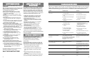
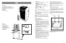
WINDOW INSTALLATION
1. Exhaust Ports
2. Air Outlet Hose (exhaust)
3. Air Intake Hose
4. Window Exhaust and Intake Adapter (2)
5. Adjustable Window Panel
Air Inlet and Air Outlet Hose: Extends from 17”
(43cm) up to 5.9 ft (1.8m)
Window Kit: Extends from 28.375” (72cm) up to
55.625” (140cm)
NOTE: Air outlet hose (exhaust) should be
mounted at A side
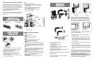
Horizontal Vertical
NOTE: Your window kit has been designed to fit most
standard vertical and horizontal window applications.
However, it may be necessary for you to improvise/modify
some aspects of the installation procedures for certain
types of windows. Please refer to measurements below:
1) Select a suitable location, making sure you have easy
access to an electrical outlet.
2) Remove the 2 hoses, 2 window exhaust adapters,
1 window panel kit.
3) To install the flexible exhaust hoses, insert the end of
the hose with the round connector into either the air
inlet or air outlet hole on the back of the unit. Turn the
hose clockwise to secure the hose into the hole. Do
this for both hoses.
4) Screw the window exhaust adapters on both hoses by
turning them clockwise.
5) Insert the air inlet window exhaust Adapter into the left
hole of the window panel kit. Then insert the air outlet
window exhaust Adapter in the right hole of the window
panel kit.
NOTE: 1. Step 3 is required only when using cooling or
dehumidification modes. In cooling mode the two hoses or
the air outlet hose can be installed for the unit to operate.
2. While operating or installing, the hoses should not be
blocked by curtains or any other obstructions.
NOTE: WHEN PLACING THE WINDOW PANELS VERTICAL,
MAKE SURE THE AIR OUTLET HOSE IS SECURED TO THE
TOP OUTLET HOLE OF THE WINDOW PANEL.
5
EXHAUST
KIT
INSTALLATION
1
2
3
4
5
A Side
Window slider kit
minimum: 28 /8(72cm)
maximum:55 /8(140cm)
Window slider kit
minimum: 28 /8(72cm)
maximum:55 /8(140cm)
1
1
3
3
ADJUSTABLE
and
OSCILLATING
LOUVERS
Manual Horizontal
Louvers
Automatic Oscillating
Louvers
REMOTE
CONTROL
PREPARATIONS