19
201842
OWNER’S MANUAL
1
2
3
4
5
6
7
Junction
Box
Black
Green
▲White
Black
White
White
Black
Transformer
White
Brown
Brown
Black
Motor
Green
370 V.A.C.
Capacitor
5 MFD
Terminal Block
Black
Thermostat
White
Red Black
Yellow
Blue
Brown
Green
Black
Brown
White
Ignition
Control
Board
Probe
♦Black
White
White
Glo-Bar
Gas Valve
Time Delay
Relay
Limit
Switch
Sail Switch
★
▲
♦
White
115 V.A.C.
(Open)
Brown
Brown
Orange
White
White
Red
★★
Note:
1
2
3
4
5
6
7
Junction
Box
Black
Green
▲White
Black
Red
White
Black
Transformer
White
Brown
Brown
Black
Brown
Motor
Green
370 V.A.C.
Capacitor
5 MFD
Yellow
Terminal Block
Black
Thermostat
White
Red Black
Yellow
Blue
Yellow
Brown
Green
Black
Brown
Orange
White
Ignition
Control
Board
Probe
♦Black
White
White
Glo-Bar
Gas Valve
Time Delay
Relay
Limit
Switch
Sail Switch
Note:
▲
♦
White
115 V.A.C.
White
(Open)
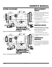
WIRING DIAGRAMS
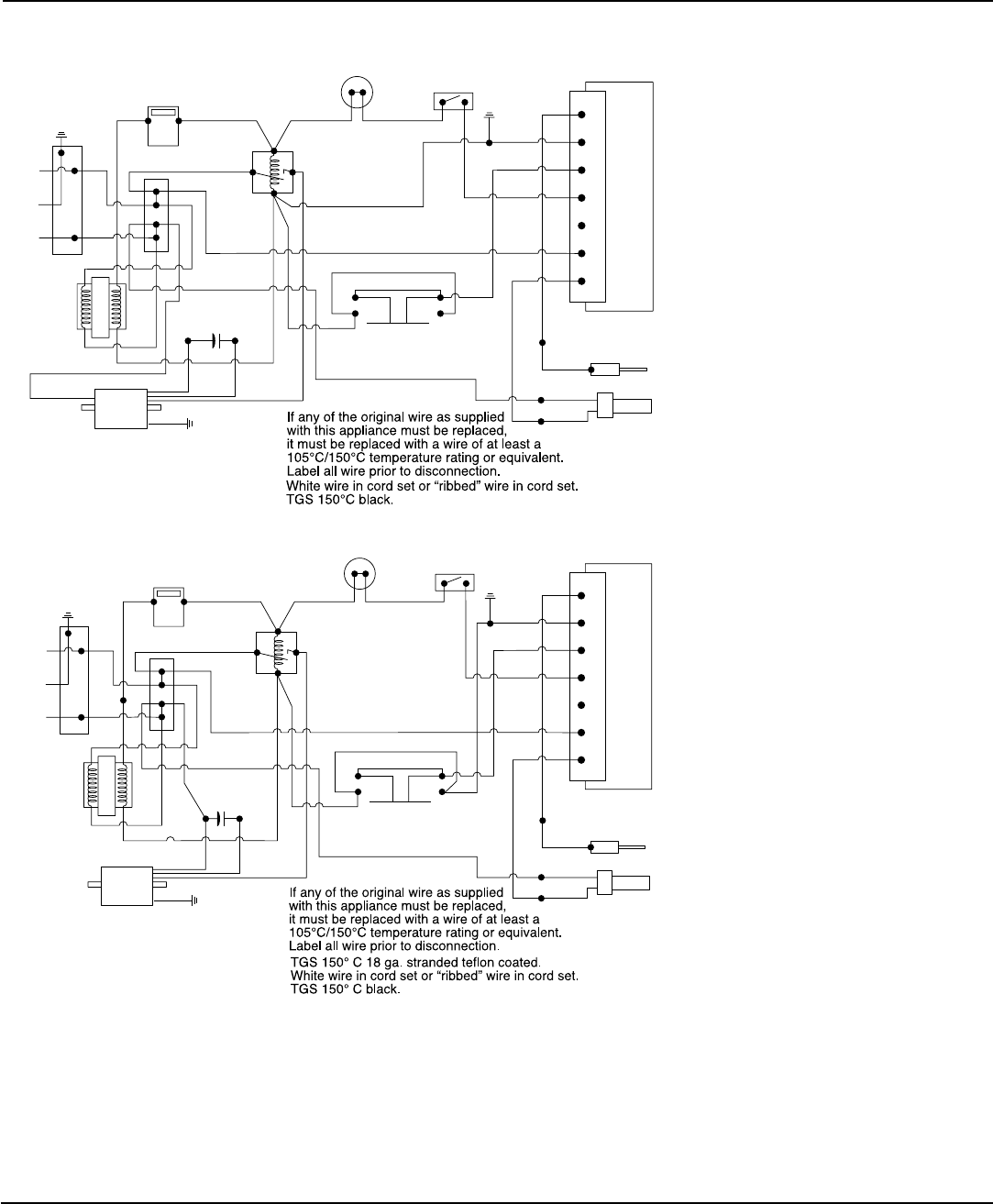
Figure 21 - Wiring Diagram (40,000 BTU/Hr Model)
Figure 20 - Wiring Diagram (25,000 BTU/Hr Model)
Note:
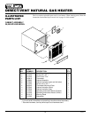
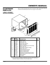
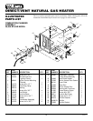
Use only original replacement parts.
This will protect your warranty coverage for
parts replaced under warranty.
All parts listed herein may be ordered from
your equipment supplier.
When ordering repair parts, always give the
following information:
• model number of your furnace
• type of gas, natural or propane/LP
• the replacement part number and de-
scription
REPLACEMENT
PART S
TECHNICAL
SERVICE
SERVICE HINTS
When Gas Pressure Is Too Low
• glo-bar glows, but burner will not ignite
When Gas Quality Is Bad
• burner will not stay lit
• burner will produce flames and soot
You may feel your gas pressure is too low or
gas quality is bad. If so, contact your local
gas supplier.
You may have further questions about in-
stallation, operation, or troubleshooting. If
so, contact your installer, a qualified service
person, or Williams Technical Help Line at
1-800-266-0993.


