


3. The furnace must be isolated from the gas supply piping system by closing its individual manual shutoff valve during any
pressure testing of the gas supply piping system at test pressures equal to or less than 1/2 psig (3.5 kPa).
Attention: If one of the above procedures results in pressures in excess of 1/2 psig (14” w.c.; 3.5 kPa) on the furnace gas valve,
it will result in a hazardous condition.
High Altitudes (US Only)
For altitudes/elevations above 2,000 feet (610 m), ratings should be reduced at the rate of 4-percent for each 1,000 feet (305 m)
above sea level by reducing the manifold pressure at 8% rate on the gas supply. Maximum altitude allowed for installation is
5500 feet (1680 m).
High Altitudes (Canada Only)
The furnace is tested according to CGA 2.17 M91 for installation between 0 and 4500 ft (0 and 1370 m) altitude. For
altitudes/elevations above 2,000 feet (610 m), ratings should be reduced at the rate of 4-percent for each 1000 feet (305 m)
above sea level by reducing the manifold pressure at 8% rate on the gas supply. Maximum altitude allowed for installation is
5500 feet (1680 m).
First Firing the Furnace
Start the furnace following the instructions given in the “Operating Instructions”. The first lighting can be difficult because of the
air trapped in the gas lines. During initial firing of the furnace, residual manufacturing grease will bake out and smoke will occur
which is not a health danger. To prevent nuisance and operation of fire alarms, ventilate the room for the first two hours of
operation.
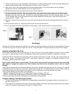
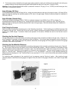
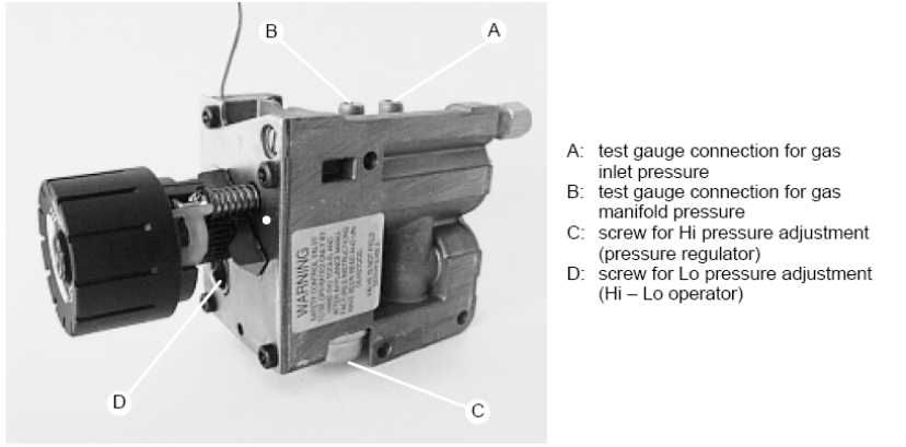
Checking the Gas Inlet Pressure
The gas inlet pressure can be measured by connecting a test gauge to the connection provided on the gas valve. (Figure 8 - A)
Once installation is complete, the gas inlet pressure must be checked. The minimum gas inlet pressure must be as shown in
“Technical Data”. After checking the gas inlet pressure, disconnect the test gauge and firmly tighten the screw of the gauge
connection, then check for gas leaks.
Checking the Gas Manifold Pressure
The gas manifold pressure can be measured by connecting a test gauge to the connection provided on the gas valve. (Figure 8 -
B). The furnace comes set from the factory at the correct manifold gas pressure. After the installation is completed, the gas
manifold pressure must be checked both in Hi and Lo input. Turn the control knob to switch the unit from Hi to Lo input. The
position of the knob in which this occurs depends on the actual room temperature. The gas manifold pressure must be as
shown in “Technical Data”. Differences of plus or minus 0.1 in. w.c. are accepted. If the Hi or Lo gas manifold pressures are
different from the values given in the “Technical Data” or are more than 0.1 in. w.c., shut off the furnace and contact a qualified
service technician.
For instructions about adjustment of the manifold Hi and Lo pressures, see the "Servicing” section. After checking the gas
manifold pressure, disconnect the test gauge and tighten firmly the screw of the gauge connection, then check for gas leaks
from it.
Figure 8
8