


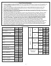
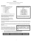
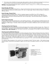
Figure 1
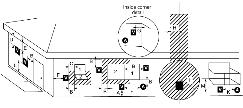
1 = Fixed/Closed 2 = Openable V = Vent Terminal A = Air Supply
A. Clearance above grade, veranda, porch, deck or
balcony 12-inches (30 cm) minimum.
K. Clearance to a mechanical air supply inlet 6 feet (1.8 m)
minimum.
(3) (3)
B. Clearance to window or door that may be opened 12-
inches (30 cm) minimum.
L. Clearance
(1)
above paved sidewalk or a paved driveway
located on public property 7 feet (2.1 m) minimum.
(3) (3)
C. Clearance to permanently closed window (minimum 12-
inches (30 cm) recommended to prevent condensation
on window.
M. Clearance under veranda, porch, deck or balcony 12-
inches (30 cm) minimum.
(2),
(3)
D. Vertical clearance to ventilated soffit located above the
terminal within a horizontal distance of 2 feet (60 cm)
from the centerline of the terminal 18-inches (46 cm)
minimum.
Notes:
(1)
A vent shall not terminate directly above a sidewalk
or paved driveway which is located between two
single family dwellings and serves both dwellings.
(2)
Only permitted if veranda, porch, deck or balcony is
fully open on a minimum of two sides beneath the
floor.
E. Clearance to unventilated soffit 12-inches (30 cm)
minimum clearance to vinyl soffit 36-inches (90 cm)
minimum.
(3)
As specified in CGA B149 installation codes (1991).
F. Clearance to outside corner 12-inches (30 cm)
minimum.
Note: Local codes or regulations may require different
clearances.
G. Clearance to inside corner 18-inches (46 cm) minimum.
H. Not to be installed above a meter/regulator assembly
within 3 feet (90 cm) horizontally from the centerline of
the regulator.
(3)
I. Clearance to service regulator vent outlet 6 feet (1.8 m)
minimum.
(3)
J. Clearance to nonmechanical air supply inlet to building
or the combustion air inlet to any other furnace 12-
inches
(
30 cm
)
minimum.
(3)
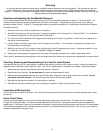
Outside Location for Vent Terminal
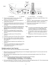
Upon delivery, check to make sure the packaging has not been damaged.
1. Remove the furnace from box/packaging taking care not to damage the paper template. This is to be used to mark the
holes for mounting the furnace.
2. After marking where the appropriate holes will be using the above mentioned template, make a 6-inch (152.4 mm)
diameter hole.
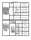
3. Cut the combustion exhaust and fresh air inlet tubes according to the wall thickness:
Air inlet tube length = wall thickness + 11/16 in. (14.4 mm)
F Flue outlet tube length = wall thickness + 3 in. 9/16 (90.5 mm)
4. Drill the mounting holes “A” (5 holes) in the wall. If the wall can receive self–tapping screws, drill 1/8-inch diameter holes.
If not, drill 1/4-inch diameter holes and use the plastic anchors provided.
5