


035-19592-001 Rev. C (0204)
Unitary Products Group 7
CONTINUOUS FLASH: This indicates that flame was sensed when
there was not a call for heat. With this fault code the control will turn on
both the inducer motor and supply air blower. A gas valve that leaks
through or is slow closing would typically cause this fault.
2 FLASHES: This indicates that the normally open pressure switch
contacts are stuck in the closed position. The control confirms these
contacts are open at the beginning of each heat cycle. This would indi-
cate a faulty pressure switch or miswiring.
3 FLASHES: This indicates the normally open pressure switch contact
did not close at the beginning of the heat cycle. This could be caused
by a number of problems faulty inducer, blocked vent pipe, broken pres-
sure switch hose or faulty pressure switch.
4 FLASHES: This indicates that a primary or auxiliary limit switch has
opened its normally closed contacts. With this fault code the control will
operate the supply air blower and inducer. This condition may be
caused by: dirty filter, improperly sized duct system, incorrect blower
speed setting, incorrect firing rate or faulty blower motor.
5 FLASHES: This fault is indicated if the normally closed contacts in the
rollout switch opens. The rollout control is manually reset. If it has
opened, check for proper combustion air, proper inducer operation, and
primary heat exchanger failure or burner problem. Be sure to reset the
switch after correcting the failure condition.
6 FLASHES: This indicates that after the unit was operating, the pres-
sure switch opened 4 times during the call for heat. If the main blower is
in a “Delay on” mode it will complete it, and any subsequent delay off
period. The vent motor continues to operate until the pressure switch
re-closes or a call for heat is removed.
7 FLASHES: This fault code indicates that the flame could not be
established. This no-light condition occurred 3 times (2 retries) during
the call for heat before locking out. Low gas pressure, faulty gas valve,
faulty hot surface ignitor or burner problem may cause this.
8 FLASHES: This fault is indicated if the flame is lost 5 times (4 recy-
cles) during the heating cycle. This could be caused by low gas pres-
sure or faulty gas valve.
9 FLASHES: Indicates reversed line voltage polarity. Both heating and
cooling operations will be affected. Check polarity at furnace and
branch.
11 FLASHES: This fault will be indicated if the rollout jumper wire con-
nection soldered into the board is broken. If this fault occurs the control
will have to be replaced. This fault may also occur in installations where
an improper ground is present. Prior to replacing control, verify that unit
is properly grounded.
STEADY ON: This fault occurs if the gas valve is energized when there
is no call for heat. If this happens the vent motor is energized and will
remain energized for 5 seconds or until the fault clears itself at which
point the vent motor de-energizes. This failure is counted as a recycle.
Check the gas valve and control for proper operation.
60-MINUTE AUTOMATIC RESET FROM LOCKOUT: This control
includes a “watchdog” type circuit that will reset from a lockout condition
after 60 minutes. Operational faults 1,6,7,8 and Steady On will be reset.
This provides protection to an unoccupied structure if a temporary con-
dition exists causing a furnace malfunction. An example would be a low
incoming gas supply pressure preventing unit operation. When the gas
pressure is restored, at some point the “watchdog” would restart the
unit and provide heat for the house.
NOTE: If a flame is detected the control flashes the LED for 1/8 of a
second and then enters a flame stabilization period.
Never bypass pressure switch to allow furnace opera-
tion. To do so will allow furnace to operate under poten-
tially hazardous conditions.
Do not try to repair controls. Replace defective controls
with UPG Source 1 Parts.
Never adjust pressure switch to allow furnace operation.
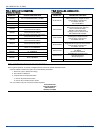
IGNITION CONTROL (P/N 031-01972-001)
Normal flame sense current is approximately
3.7 microamps DC (µa)
Low flame signal control lockout point is
0.9 microamps DC (µa)
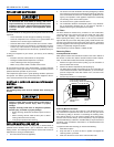
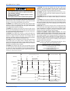
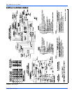
FIGURE 8: Furnace Control Event Schedule
Thermostat Calling for Heat
Thermostat Satisfied
(Seconds)
THERMOSTAT
INDUCER
IGNITOR
MAIN VALVE
HUMIDIFIER
ELECTRONIC
AIR CLEANER
CIRCULATING
BLOWER
OFF
OFF
OFF
OFF
OFF
OFF
OFF
ON
ON
ON
ON
OFF
OFF
OFF
OFF
ON
ON
ON
OFF
OFF
OFF
OFF
OFF
OFF
OFF
15 Sec.
Post
Purge
Fan on Delay
30 Seconds
0
2
17 22
52
0
60, 90, 120, 180 SEC.
Selectable Fan Off Delay