


035-19592-001 Rev. C (0204)
Unitary Products Group 5
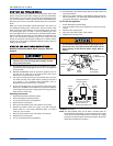
How to Clean your Filter
High-velocity filters may be cleaned with a vacuum cleaner or washed
with a garden hose. Be sure to shake off excess water and allow filter to
completely dry before re-installing the filter.
Blower Care
Even with good filters properly in place, blower wheels and motors will
become dust laden after long months of operation. The entire blower
assembly should be inspected annually. If the motor and wheel are
heavily coated with dust, they can be brushed and cleaned with a vac-
uum cleaner. If the blower cannot be properly cleaned without removing
it from the furnace, then this service must be performed by a qualified
service agency.
Motor Lubrication
The motors in these furnaces are permanently lubricated, and do not
require periodic oiling.
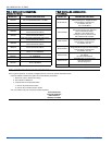
SEQUENCE OF OPERATION
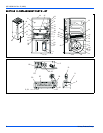
The following describes the sequence of operation of the furnace. Refer
to Figure 1 for component location.
Continuous Blower
Cooling/heating thermostats have a fan switch that has an ON and
AUTO position. In the ON position the thermostat circuit is completed
between terminals R and G. The motor will operate on the speed tap
wire that is connected to the cooling terminal on the control board. To
obtain a constant air circulation at lower flow rate, change the high-
speed wire to either the medium speed wire or the low speed wire.
Intermittent Blower - Cooling
Cooling/heating thermostats have a fan switch that has an ON and
AUTO position. In the AUTO position the thermostat circuit is completed
between terminals R and G when there is a call for cooling. The motor
will operate on the speed tap wire that is connected to the cooling termi-
nal on the control board. The fan off setting is fixed at 60 seconds for
SEER enhancement.
Heating Cycle
When the thermostat switch is set on HEAT and the fan is set on AUTO,
and there is a call for heat, a circuit is completed between terminals R
and W of the thermostat. When the proper amount of combustion air is
being provided, the pressure switch will close, the ignition control pro-
vides a 17-second warm-up period, the gas valve then opens, the gas
starts to flow, ignition occurs and the flame sensor begins its sensing
function. The blower motor will energize 30 seconds after the gas valve
opens, if a flame is detected. Normal furnace operation will continue
until the thermostat circuit between R and W is opened, which causes
the ignition system and gas valve to de-energize and the burner flames
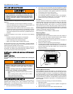
to be extinguished. The vent motor will operate for 15 seconds and the
blower motor will operate for the amount of time set by the fan-off delay
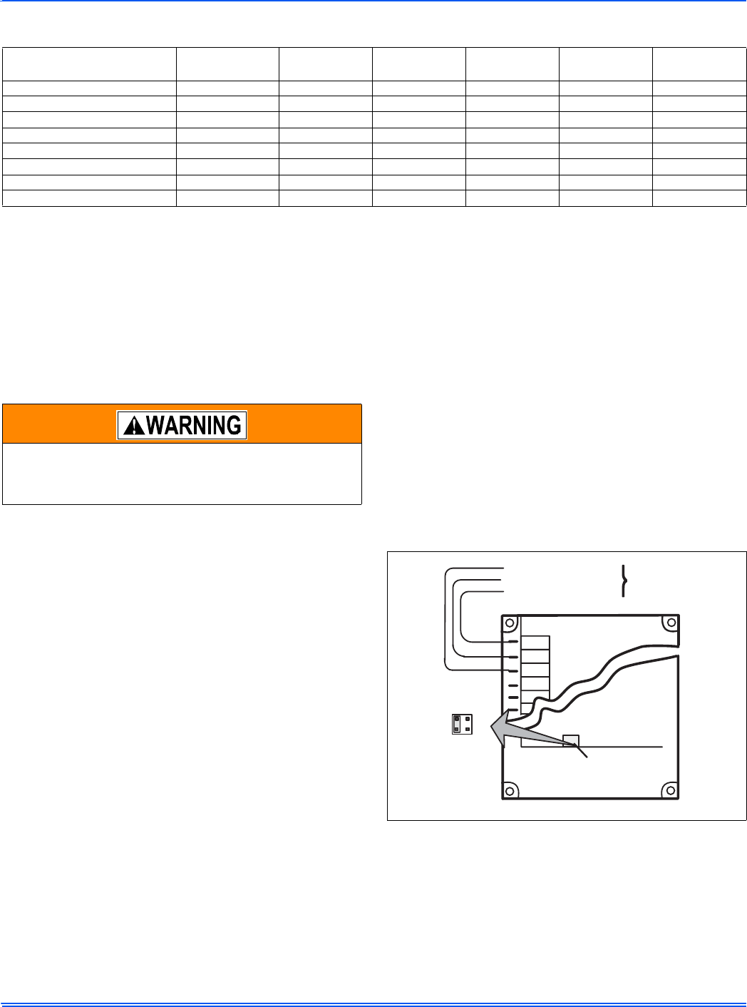
jumper located on the control board. See Figure 7. The heating cycle is
complete, and ready for the start of the next heating cycle.
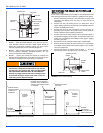
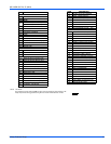
TABLE 1:
Filter Sizes
Input / Output
BTU/H (kW)
CFM (cm/m)
Cabinet
Size
Side (in) Side (mm) Bottom (in) Bottom (mm)
40/37 (11.71/10.84) 1000 (28.32) 14-1/2” (A) 16 x 25 406 x 635 14 x 25 356 x 635
60/55/ (17.57/16.10) 1000 (28.32) 17-1/2” (B) 16 x 25 406 x 635 16 x 25 406 x 635
80/75/ (23.42/21.96) 1200 (33.98) 17-1/2” (B) 16 x 25 406 x 635 16 x 25 406 x 635
80/75/ (23.42/21.96) 1600 (45.31) 21” (C) 16 x 25 406 x 635 20 x 25 508 x 635
100/95 (29.28/27.82) 1400 (39.64) 21” (C) 16 x 25 406 x 635 20 x 25 508 x 635
100/95 (29.28/27.82) 2000 (56.63) 21” (C) (2) 16 x 25 (2) 406 x 635 20 x 25 508 x 635
120/112/ (35.14/32.80) 2000 (56.63) 24-1/2” (D) (2) 16 x 25 (2) 406 x 635 22 x 25 559 x 635
140/130/ (40.99/38.06) 2000 (56.63) 24-1/2” (D) (2) 16 x 25 (2) 406 x 635 22 x 25 559 x 635
Make sure you DO NOT move the clip on weight on the
indoor fan wheel when cleaning the wheel. This weight is
used to balance the wheel. Moving the weight will cause
the fan wheel to vibrate.
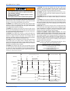
FIGURE 7: Typical Heat/Cool Speed Tap Connections
RED-LOW SPEED
BLU-MEDIUM SPEED
BLK-HIGH SPEED
MOTOR LEADS
BLK
BLU
RED
60
180
120
FAN OFF
ADJUSTMENT
SWITCHES
COOL
HEAT
PARK
PARK
LINE
XM
90