


3
INSTALLER MUST READ FOR PROPER
INSTALLATION
•WiringharnessesandaUniversal21D64-2ignitorare
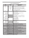
included in this package. Refer to the enclosed “Cross
ReferenceandHarnessApplicationChart”(PartNumber
37-7077) for harness selection and ignitor application
information. Ignitor installation instructions are in the
UNIVERSAL21D64-2Ignitorpackageincludedwiththiskit.
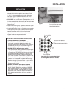
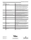
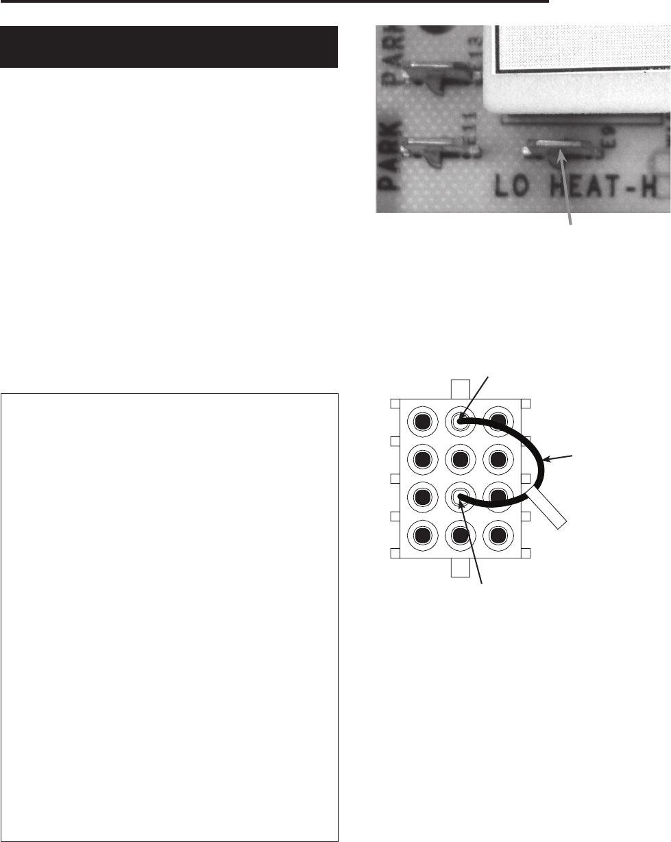
•IMPORTANT: For continuous fan speed operation, one of
the unused parked motor taps must be connected to the
low heat speed terminal. Failure to do this will result in the
blower not energizing in the constant fan mode operation.
Refertogure1.
•InstallermustreadPage(6)“Operation”andfollowoption
switch setting for proper control operation.
•Incertainapplicationsitmaybenecessarytoremovethe
control board from the cover to be mounted in the space
allowed. Standoffs supplied in the package must be
installed before the control board can be mounted.
•4Blowerleadextensionsareincludedinthekitifextra
length is needed to complete installation.
INSTALLATION
For continuous fan speed
connect one of the unused
parked terminals here
Figure 1
290600
J
Pin11(ROIn)
Pin 5 (RO Out)
Jumper0151-290600
(for Trane and American
Standard applications only)
Figure 2. 12 Pin Connector (back view)
onexistingWireHarnessinFurnace
IMPORTANT OEM REPLACEMENT INSTRUCTIONS
•TRANE and AMERICAN STANDARD
ForallTRANEandAMERICANSTANDARDfurnaces
only:Installjumper0151290600(includedinthis
package)intothebackofthefurnace12pinconnector
harnessfrompin5topin11asshowninFigure2.
Make sure jumper snaps into the connector securely.
• RHEEM / RUUD (1994 and earlier models)
Ifthefurnacecontrolbeingreplacedhas2greenlights
andNOamberlight(furnacedatecode3294orearlier)
aFlameSensorKit,RHEEMPartNumber62-24044-71
(not available from White-Rodgers) is required. Install
the flame sensor and plug the flame sensor lead into
pin 7 of the connector on the furnace as detailed in the
Rheem Flame Sensor Kit instructions. Plug the furnace
connectorintoharness“B”(includedinthispackage).
Plugtheotherendofharness“B”intothenewmodule.
Attachtheorangewirefromharness“B”(3/16”female
spade terminal) to FS on the new module to complete
the flame sense circuit.
• BRYANT / CARRIER / DAY & NIGHT / PAYNE
ThiskitwillnotreplaceBRYANT/CARRIER/DAY&
NIGHT/PAYNEHK42FZ013modulesorCARRIER
/BDPmodulesusingan11pin(straight)connector.
Refer to the enclosed “Cross Reference and Harness
ApplicationChart”(InstructionsheetPartNumber37-
7077) included with this kit for the list of modules it
replaces.