


2
SPECIFICATIONS
MOUNTING AND WIRING
All wiring should be installed by a qualified heating and air
conditioning contractor or licensed electrician, according to
local and national electrical codes and ordinances.
Thecontrolmustbesecuredtoanareathatwillexperiencea
minimumofvibrationandremainbelowthemaximumambient
temperature rating of 176°F. The control is approved for
minimumambienttemperaturesof-40°F.
When mounting the control, any orientation is acceptable.
Choose a location that will not damage, obstruct or place
stress on the control’s terminations, system wiring harness or
system components. After finding a suitable location, drill four
(4)1/8”holesformountingcontrol.Toensurepropermounting
hole locations, use the control as a template. When drilling
the holes, take care so that the transformer, wiring harness or
other system components are not damaged. Four (4) #8 sheet
metal screws are provided to complete the installation.
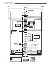
Refer to the wiring diagram and wiring table when connecting
the 50M56U-843 control to other components of the system.
UL approved, 105°C rated 18 gauge, stranded, 2/64” thick
insulation wire is recommended for all low voltage safety circuit
connections.
UL approved 105°C rated 16 gauge min., stranded, 4/64”
thick insulation wire is recommended for all line voltage
connections.
After installation or replacement, follow appliance manufacturer’s
recommended installation or service instructions to ensure
proper operation.
ELECTRICAL RATINGS [@ 77°F (25°C)]:
Input Voltage:25VAC50/60Hz
Max.InputCurrent@25VAC: 0.45 amp
Relay Load Ratings:
ValveRelay: 1.5amp@25VAC50/60Hz0.6pf
IgnitorRelay:6.0amp@120VAC50/60Hz(resistive)
InducerRelay:2.2FLA–3.5LRA@120VAC
CirculatorRelay:14.5FLA–25.0LRA@120VAC
Flame Current Requirements:
Minimumcurrenttoinsureamedetection:1µaDC*
Maximumcurrentfornon-detection:0.1µaDC*
Maximumallowableleakageresistance:100Mohms
*MeasuredwithaDCmicroammeterintheameprobelead
OPERATING TEMPERATURE RANGE:
-40°to176°F(-40°to80°C)
HUMIDITY RANGE:
MOUNTING:
Surface mount multipoise
Timing Specs:(@60Hz)
maximum
Flame Establishing Time: 0.8 sec
FlameFailureResponseTime: 2.0sec
GasesApproved:Natural,Manufactured,Mixed,Liquied
Petroleum,andLPGasAirMixturesareallapprovedforuse.
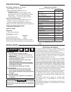
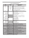
TIMING SPECIFICATIONS
(All times are in seconds, unless noted otherwise
50M56U-843
Pre-Purge 30
Initial Ignitor Warm-Up
(1st64attempts)
17
MaximumIgnitorWarm-Up 19
Ignition Activation Period 2
Trial for Ignition Period 4
Retries 2
Recycles 3
ValveSequencePeriod 12
Interpurge 60
Post-Purge 25
Lockout Time 275
HeatDelay-To-Fan-On 30
HeatDelay-To-Fan-Off 100/150*
CoolDelay-To-Fan-On 6
CoolDelay-To-Fan-Off 45
Auto Reset 60 minutes
*Thesetimeswillvarydependingonoptionswitch
position. See OPERATION section for further infor-
mation.
Do not short out terminals on gas valve or primary
control. Short or incorrect wiring may damage the
thermostat.
CAUTION
!
WARNING
!
FIRE HAZARD
• Donotexceedthespeciedvoltage.
• Replaceexistingcontrolwithexactmodeland
dash number.
• Protectthecontrolfromdirectcontactwithwater
(dripping, spraying, rain, etc.).
• Ifthecontrolhasbeenindirectcontactwith
water, replace the control.
• Labelallwiresbeforedisconnectionwhenserv-
icing controls. Wiring errors can cause improper
and dangerous operation.
• Routeandsecurewiringawayfromame.
SHOCK HAZARD
• Disconnectelectricpowerbeforeservicing.
• Ensureproperearthgroundingofappliance.
• Ensureproperconnectionoflineneutralandline
hot wires.
EXPLOSION HAZARD
• Shutoffmaingastoapplianceuntilinstallation
is complete.
INSTALLATION