


7
SYSTEM LOCKOUT AND
DIAGNOSTIC FEATURES
SYSTEM LOCKOUT FEATURES
When system lockout occurs, the gas valve is de-ener-
gized, the circulator blower is energized at heat speed,
and, if flame is sensed, the inducer blower is energized.
The diagnostic indicator light will flash or glow continu-
ously to indicate system status. (System lockout will
never override the precautionary features.)
To reset the control after system lockout, do one of the
following:
1. Interrupt the call for heat or cool at the thermostat for
at least one second but less than 20 seconds (if flame
is sensed with the gas valve de-energized, interrupt-
ing the call for heat at the thermostat will not reset the
control).
2. Interrupt the 24 VAC power at the control for at least
one second. You may also need to reset the flame
rollout sensor switch.
3. After one hour in lockout, the control will automatically
reset itself.
DIAGNOSTIC FEATURES
The 50A55 control continuously monitors its own opera-
tion and the operation of the system. If a failure occurs, the
LED will indicate a failure code as shown below. If the
failure is internal to the control, the light will stay on
continuously. In this case, the entire control should
be replaced, as the control is not field-repairable.
If the sensed failure is in the system (external to the
control), the LED will flash in the following flash-pause
sequences to indicate failure status (each flash will last
approximately 0.25 seconds, and each pause will last
approximately 2 seconds).
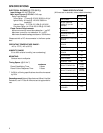
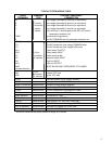
1 flash, then pause System lockout
2 flashes, then pause Pressure switch stuck closed
3 flashes, then pause Pressure switch stuck open
4 flashes, then pause Open limit switch
5 flashes, then pause Open rollout switch
6 flashes, then pause 115 Volt AC power reversed/
improper ground
7 flashes, then pause Low flame sense signal
Continuous flashing Flame has been sensed when
(no pause) no flame should be present (no
call for heat)
The LED will also flash once at power-up.
COOL MODE
In a typical system, a call for cool is initiated by closing the
thermostat contacts. This energizes the 50A55 control
and the compressor. The cool delay-to-fan-on period
begins. After the delay period ends, the optional elec-
tronic air cleaner is energized, and the circulator fan is
energized at cool speed. After the thermostat is satisfied,
the compressor is de-energized and the cool mode delay-
to-fan-off period begins. After the delay-to-fan-off period
ends, the circulator fan and electronic air cleaner (op-
tional) are de-energized.
MANUAL FAN ON MODE
If the thermostat fan switch is moved to the ON position,
the circulator fan (cool speed) and optional electronic air
cleaner are energized. When the fan switch is returned to
the AUTO position, the circulator fan and electronic air
cleaner (optional) are de-energized.
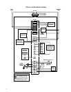
TWINNING INTERFACE
If the control has six screw terminals, one of which is
designated TWIN, the control is equipped with a single
wire twinning interface. If twinning is used, either control
will process a call for heat, cool or fan as described above.
However, after the heat-, cool-, or fan-on delay time
expires, both units will energize the circulator blowers at
the same time. Likewise, after the heat-, cool-, or fan-off
delay time expires, both units will de-energize the circula-
tor blowers at the same time. This allows for proper air flow
to be obtained. To assure proper control operation, both
controls must share a common transformer ground (TR).
To enable twinning, do the following.
1. Power supplied to both furnaces must be from the
same phase of the incoming 120 VAC power.
2. Connect the TWIN screw terminals on the 50A55-143
of the furnaces to be twinned to each other using a
single wire (14-22 AWG.).