


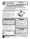
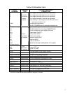
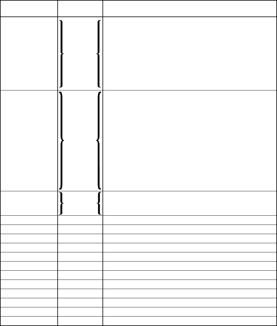
5
50A55
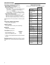
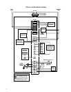
TERMINAL
TERMINAL
TYPE
SYSTEM COMPONENT
CONNECTION
TYPICAL SYSTEM WIRING TABLE
* maximum recommended flame probe wire length is 36 inches.
W
G
R
Y
TWIN
C
MV (2 terminals)
TR
TH
RO1
RO2
FP
PS
HLI
HLO
GND
(unused terminal)
IND
IGN
COOL
HEAT
PARK (2 terminals)
LINE
XFMR
EAC (optional)
HUM (optional)
CIR N
LINE N
XFMR N
EAC N (optional)
HUM N (optional)
Terminal
block with
captive
screws
12-pin
connector
& harness
2-pin
connector
& harness
spade terminal
spade terminal
spade terminal
spade terminal
spade terminal
spade terminal
spade terminal
spade terminal
spade terminal
spade terminal
spade terminal
spade terminal
low voltage thermostat W terminal (or equivalent)
low voltage thermostat G terminal (or equivalent)
low voltage thermostat R terminal (or equivalent)
low voltage thermostat Y terminal (or equivalent)
(2nd wire from Y terminal goes to 24 VAC HOT side of
compressor contactor coil)
one wire twinning terminal
24 VAC COMMON side of compressor contactor coil
gas valve (both gas solenoids are connected in parallel)
24 VAC transformer (low voltage COMMON side)
24 VAC transformer (low voltage HIGH side)
rollout switch OUTPUT
rollout switch INPUT
flame sensor probe*
pressure switch INPUT
high limit INPUT
high limit OUTPUT
MUST BE RELIABLY GROUNDED TO CHASSIS
inducer HOT side
ignitor HOT side
circulator blower COOL SPEED terminal
circulator blower HEAT SPEED terminal
unused circulator blower terminals
input voltage (120 VAC) HOT side
24 VAC transformer line voltage HOT side
electronic air cleaner HOT side
humidifier HOT side
circulator blower NEUTRAL terminal
input voltage (120 VAC) NEUTRAL side
24 VAC transformer line voltage NEUTRAL side
electronic air cleaner NEUTRAL side
humidifier NEUTRAL side