


2
WIRING
All wiring should be done in accordance with local and national electrical codes and ordinances.
If a wiring diagram is supplied with the heating equipment,
follow those instructions. If none is available, several diagrams
are presented on this sheet which show different wiring meth-
ods for these Silent Operator relays. Always be sure that the
supply voltage agrees with the voltage rating of the Silent
Operator relay.
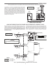
The proper location and method of installation for the Silent
Operator relay shall be determined by the manufacturer of the
heating equipment. A dimensional drawing of the Silent Operator
relay is shown at the right.
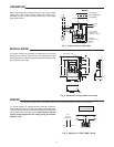
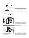
Basic Silent Operator components are a line-to-low voltage
transformer, a low voltage bimetal heater, an ambient com-
pensating bimetal, and a normally open SPST line voltage
snap-action switch.
INSTALLATION
OPERATION
Fig. 1. Internal wiring of Type 24A07
WHITE
WIRING
Line Voltage
Line Voltage Field
Low Voltage
TRANSFORMER
YELLOW
BLACK
BLUE
HEATING
LOAD
BIMETAL HEATER
AMBIENT
COMPENSATING
BIMETAL
LINE VOLTAGE
SNAP SWITCH
(NORMALLY OPEN)
RED
LINE
7/16"
15/16"
1 3/8"
15/32"
9/16"
2 11/16"
2 13/32"
9/16"
3 11/32"
4 1/16"
1 15/32"
3 7/16"
Fig. 2. Dimensions of Type 24A07 Level Temp
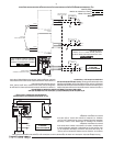
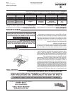
BREAK-OFF TABS
Fig. 3. Diagram of “LEVEL TEMP” Wiring
RED WHITE
LOW
VOLTAGE
THERMOSTAT
BLACKBLUE
ENILDAOL
YELLOW
L1
L2
MAKE L2 “HOT”
ON 120V MODELS