


3
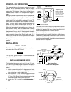
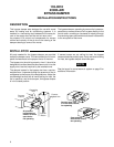
4. Use access-mounting plate as a template. Hold plate
against duct and mark the four hole locations for
attaching plate to duct. Be sure slotted hole in center
of plate is over point “X” (Fig. 1) and that edge of
plate is parallel with edge of duct. Then drill the four
holes to take #10 sheet metal screws.
5. Cut out 4” x 8” access hole through which damper vane
is to be installed. Access hole should be centrally
located between the four mounting holes.
6. Attach indicator wheel to damper shaft with two 5-40
screws with lockwashers.
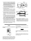
7. Cut damper vane to duct size, allowing
1
⁄8” minimum
clearance between duct and vane at all points. (If
required, snip notches in vane to clear protruding
sheet metal screws used to mount bearing plate.)
8. Attach vane brackets to locate damper shaft on exact
center line of damper vane. (Dimension from center
line of vane to center of holes for attaching vane
brackets is
17
⁄32”.) Then start 8-32 set screws into vane
brackets.
9. Insert damper shaft through access-mounting plate,
then through vane brackets. Holding indicator wheel
flush against access-mounting plate, lock damper
shaft to vane by tightening set screws, being sure to
leave
1
⁄8” minimum clearance between edge of
vane and access-mounting plate as shown.
10.Install vane through hole in duct by turning vane
sideways and slipping damper shaft into slot in bearing
plate on opposite side of duct. Push indicator wheel
flush against access-mounting plate and spin indica-
tor wheel to assure free turning of vane. Then attach
access-mounting plate to duct and cut off damper
shaft so it extends 1” past bearing plate.
#10 Sheet
Metal Screws
Damper Vane
4” x 8”
Access Hole
Indicator
Wheel
Damper
Shaft
Wing Nut
Motor
Access-
Mounting Plate
Damper Vane
Access-Mounting
Plate
Indicator
Wheel
Vane
Brackets
8-32
Set Screws
#10 Sheet
Metal Screws
5-40 Screws
With
Lockwashers
Leave
1
⁄
8
” minimum clearance
when tightening set screw
Do not cut off
damper shaft until
vane is installed
15
⁄
16
”
Notches to clear
sheet metal
screws (if required)
11.Motor is shipped in closed position. Turn indicator
wheel so that yoke on bottom of motor slips into
square holes on indicator wheel when motor is placed
into position. Tighten motor firmly with wing nuts. (The
word “closed” should be visible on the indicator wheel.)
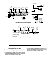
WIRING
All wiring must conform to local and national electri-
cal codes.
If the furnace manufacturer recommends a wiring dia-
gram, follow such instructions. If none are available, the
following diagrams show suggested circuits for Type
2061 Damper motors in conjunction with two-wire thermo-
stats (.2 Amp anticipator) and other related controls.
For best connections, use #18 Thermostat wire. #16 will
also work satisfactorily.
Make connections to screw terminals according to wiring
diagram.
To check motor operation without thermostat connected,
jumper 2 to 4 to open motor. Remove jumper to close
motor.
NOTE
The WR S81-0125 Transformer (40 VA) will handle up to
4 damper motors. The WR S81-0126 (20VA) will handle
up to 2 damper motors.