


2
Point “X”
(locate exactly
opposite
1
⁄
2
” hole)
Centerlines
of Duct
1
⁄
2
” Dia. Hole
#10 Sheet
Metal Screws
Bearing
Plate
15
⁄
16
”
1
3
22
4
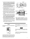
110-280 or
120-280
Thermostat
2061 Two-Wire
Damper Motor
INTERNAL WIRING
EXTERNAL WIRING
Side “A” of
Motor Switch
Side “B” of
Motor Switch
Warp Switch
Heater
Warp Switch
Contacts
(Normally Closed)
Motor
Contact
“C”
Transformer
Line
To auxiliary circuit
for operating oil
burner or gas valve
NOTE: If same
transformer powers both
the auxiliary circuit and the
damper motor, connect
the auxiliary circuit to
terminals 1 and 3 instead
of 2 and 3.
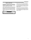
PRINCIPLE OF OPERATION
This schematic shows the damper motor in the closed
position. As the thermostat calls for heat, the damper
motor is energized as a circuit is made through side “A” of
motor switch. (At the same, time a circuit is made through
the warp switch heater.) The damper motor begins to
open.
Before the damper motor reaches the full open position,
side “B” of motor switch closes (providing a low voltage
auxiliary circuit for starting oil burner or opening gas
valve), side “A” of motor switch makes with contact “C”,
and the warp switch heater opens the warp switch con-
tacts. The warp switch heater remains energized and
keeps the warp switch contacts open as long as the
thermostat calls for heat.
When the thermostat is satisfied, the circuit through the
warp switch is broken. After this heater cools for a short
time, the warp switch contacts close, energizing the
damper motor through side “A” of motor switch. Just after
the damper motor begins closing, side “B” of motor switch
opens (breaking the auxiliary circuit), while side “A” of
motor switch makes with contact 4 just before the damper
motor fully closes.
The damper motor draws no current while in the closed
position.
The system is so wired so that if any one zone still calls for
heat, the burner stays on. When all thermostats are
satisfied, all dampers will have closed, and the circuit
broken to the gas valve or oil burner control.
The blower in the furnace operates as in any conven-
tional, unzoned hot air system. When the air in the plenum
is warmed to a set temperature, the fan control turns the
blower on. When the air temperature drops, the fan
control turns the blower off. The addition of zoning has not
affected normal fan operation.
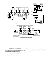
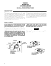
INSTALLATION
DUCT LAYOUT
This illustration shows a typical layout for a zoned warm
air system using Zone-Air Controls.
The use of a bypass damper is recommended. See
page 6 for details.
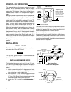
INSTALLING DAMPER MOTOR
The following instructions apply for 6, 8, and 10” ducts.
(For round ducts and rectangular ducts under 6” a special
bracket is available which replaces the access-mounting
plate.)
1. Select a convenient position for damper motor instal-
lation on duct work to each zone. Carefully locate and
mark center line on each side of duct.
2. Mark location for
1
⁄2” hole. Also mark locations for holes
to attach bearing plate by measuring
15
⁄16” from center
of
1
⁄2” hole. Drill all three holes and attach bearing plate
with two #10 sheet metal screws provided.
3. Locate point “X” on center line exactly opposite
1
⁄2”
hole.
NOTE
Bypass Duct
Return Duct
Outlet
Zone 3
Outlet Zone 1
Outlet
Zone 2
Outlet
Zone 4
Supply Duct
DAMPER
MOTORS
Zone 1
Zone 2
Zone 3
Zone 4
BypassDamper
Parts Group
133-0010
Duct Layout For
4 Zone Warm Air System