


6
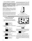
ATTACH THERMOSTAT TO SUBBASE
WE RECOMMEND THAT YOU SET OPTION SWITCHES
TO DESIRED POSITION BEFORE ATTACHING ON
SUBBASE (see OPERATION). WE ALSO RECOM-
MEND THAT YOU PROGRAM THE THERMOSTAT
WITH BATTERY INSTALLED BEFORE ATTACHING
ON SUBBASE (see OPERATION GUIDE for program-
ming instructions).
POWER TO THERMOSTAT MUST BE OFF BEFORE
ATTACHING THERMOSTAT TO WALL. FAILURE TO
TURN OFF POWER BEFORE ATTACHING THERMO-
STAT MAY CAUSE EQUIPMENT DAMAGE DUE TO
RAPID COMPRESSOR CYCLING.
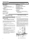
To attach thermostat to subbase, line up the plastic snap
guides at the top of the thermostat and the 4 connector
pins on the thermostat with the connectors near the top
right section of the subbase (when viewed from the front).
Gently pivot the thermostat down until the 9-pin connec-
tors and the plastic snaps lock into place (see fig. 7). Be
gentle when attaching thermostat. If the thermostat
does not seem to be attaching to the subbase easily,
make sure that the connector pins and plastic snaps are
properly aligned, and that excess wire is pushed into the
wall. Damage to the thermostat may occur if force is
used.
OPERATION
ENGAGE TWO UPPER GUIDES;
PIVOT DOWN
Figure 7. Attaching thermostat to subbase
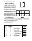
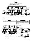
SYSTEM CONFIGURATION
SET OPTION SWITCHES
1. Single Stage Compressor Heat Pump System —
with reversing valve energized through B or O termi-
nals
2. Two Compressor (Split) or Two Speed Compres-
sor System
3. Economizer Enabled for 1st Stage Cooling — use
with fresh air damper to conserve energy by bringing
temperature down more slowly
4. Energy Management Recovery Option (Enabled)
5. Total Keypad Lockout (Enabled)
Option switches #1, #2, and #3 should be changed (if
required), programming should be completed, and bat-
tery should be installed before changing option switch #4.
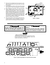
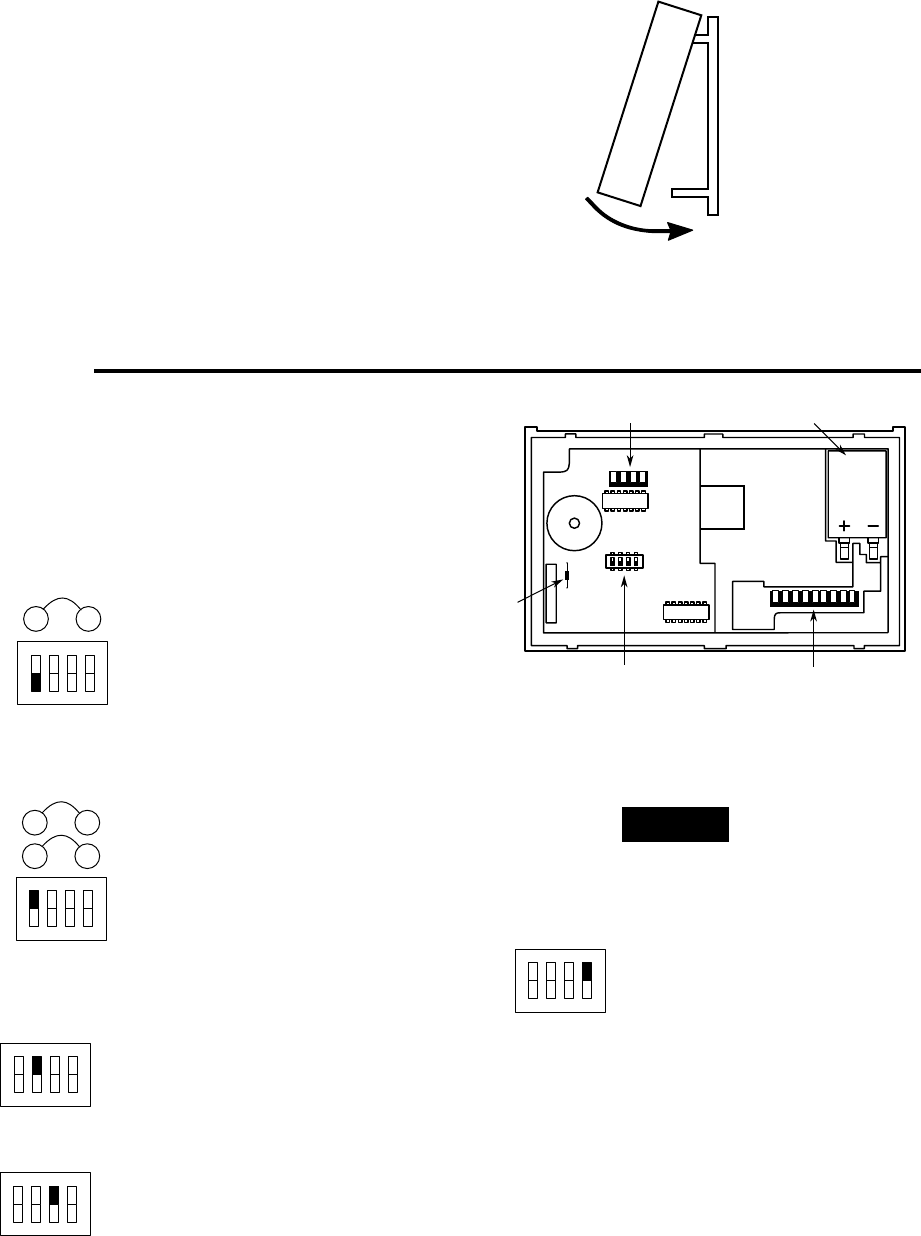
REVERSING VALVE DELAY OPTION
The diode designated as CR5 controls whether or not
there will be a delay in reversing valve switching (see fig.
8). With the diode installed and operational, there is no
delay. If the diode is not operational or is disconnected,
there will be a six-second delay before the reversing valve
is switched.
Figure 8. Back of thermostat
Option switches 9-pin connector
4-pin connector
Battery
Option
diode
(CR5)
ON
1234
Switch #1 OFF
Switch #2 (see step 3)
Switch #3 (see step 4)
Switch #4 (see step 5)
W1 Y1
Field jumper W1 & Y1
ON
1234
Switch #1 ON
Switch #2 (see step 3)
Switch #3 (see step 4)
Switch #4
(
see step 5
)
W1 Y1
Field jumper W1 & Y1
W2 Y2
Field jumper W2 & Y2
ON
1234
Switch #1 (see steps 1 & 2)
Switch #2 (see step 3)
Switch #3 ON
Switch #4
(
see step 5
)
ON
1234
Switch #1 (see steps 1 & 2)
Switch #2 ON
Switch #3 (see step 4)
Switch #4
(
see step 5
)
NOTE
ON
1234
Switch #1 (see steps 1 & 2)
Switch #2 (see step 3)
Switch #3 (see step 4)
Switch #4 ON