


4
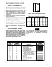
2. Connect wires beneath terminal screws on sub-
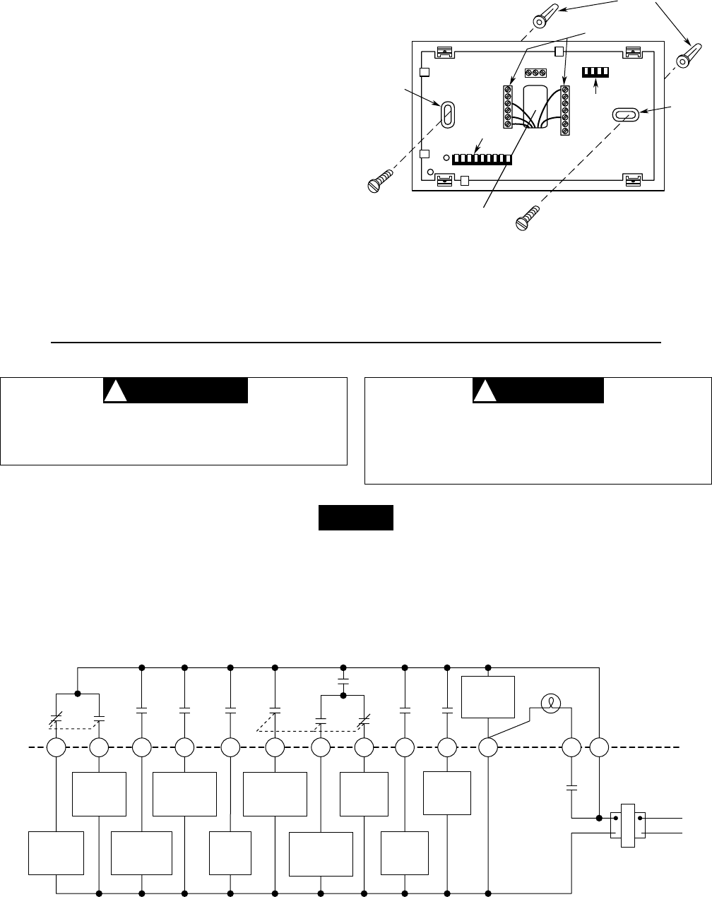
base using appropriate wiring schematic (see figs.
3 through 6).
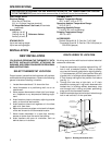
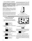
3. Place subbase over hole in wall and mark mounting
hole locations on wall using subbase as a template.
4. Move subbase out of the way. Drill mounting holes.
5. Fasten subbase loosely to wall, as shown in fig. 3,
using two mounting screws. Place a level against
bottom of subbase, adjust until level, and then tighten
screws. (Leveling is for appearance only and will not
affect thermostat operation.) If you are using existing
mounting holes, or if holes drilled are too large and do
not allow you to tighten subbase snugly, use plastic
expansion plugs to secure subbase.
6. Push excess wire into wall and plug hole with a fire-
resistant material (such as fiberglass insulation) to
prevent drafts from affecting thermostat operation.
S1
S2
S3
Mounting
hole
Pull wires through
this opening
Connect wires under
terminal screws
Mounting
hole
4-pin connector
9-pin connector
O
B
Y1
Y2
C
G
W1
R
W2
Expansion
plugs
Figure 3. Subbase
E1
E2
L
A1
DO NOT EXCEED MAXIMUM VOLTAGE OR
CURRENT RATINGS. FIRE, PERSONAL IN-
JURY, AND/OR EQUIPMENT DAMAGE COULD
RESULT.
To prevent electrical shock and/or equipment
damage, disconnect electrical power at the main
fuse box until installation is complete. Verify
CAUTION
!
WARNING
!
NOTE
power is off with a voltmeter.
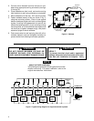
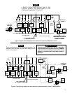
The following wiring diagram shows typical terminal iden-
tification and wiring. For proper installation, refer to the
original manufacturers' instructions.
L
C R
B
O
Changeover
Energized
In Heat
Changeover
Energized
In Cool
Compressor
Contactor
Stage 1
Fan
Relay
Heat
Relay
Stage 1
Damper
Motor
Thermostat
Control
Circuit
Compressor
Contactor
Stage 2
24vAC
120vAC
Hot
Neutral
THERMOSTAT
SYSTEM
Y1 Y2 W1
A1
E1
Emergency
Relay
Constant
Output
E2
Emergency
Relay
Switched
Output
TRANSFORMER
Malfunction
Light
System
Monitor
Switch
Figure 4. Typical wiring diagram for single transformer systems
G
Heat
Relay
Stage 2
W2