


4
RHMV
THERMOSTAT
SYSTEM
W
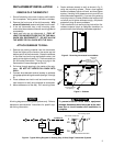
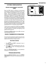
Figure 5. Typical Wiring Diagram for Millivolt Systems
6
Millivolt
System
6
MV
W
RH
Thermostat Terminal Connections
From millivolt system
W
From millivolt system
MV
ATTACH THERMOSTAT TO SUBBASE
POWER TO THERMOSTAT MUST BE OFF BE-
FORE ATTACHING THERMOSTAT TO WALL.
FAILURE TO TURN OFF POWER BEFORE AT-
TACHING THERMOSTAT MAY CAUSE EQUIP-
MENT DAMAGE DUE TO RAPID COMPRESSOR
CYCLING.
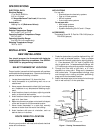
To attach thermostat to subbase, line up the plastic snap
guides at the top of the thermostat and the six connector
pins on the thermostat with the connectors near the top of
the subbase. Gently pivot the thermostat down until the
plastic snaps lock into place (see fig. 7). Be gentle when
attaching thermostat. If the thermostat does not seem
to be attaching to the subbase easily, make sure that the
connector pins and plastic snaps are properly aligned,
and that excess wire is pushed into the wall. Damage to
the thermostat may occur if force is used.
CAUTION
!
ENGAGE TWO UPPER GUIDES;
PIVOT DOWN
Figure 7. Attaching thermostat to subbase
RHMV
24vAC
120vAC
Hot
Neutral
THERMOSTAT
SYSTEM
W
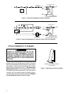
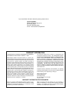
Figure 6. Typical Wiring Diagram for Heat Only, 3-Wire, Zone Valve Systems
TRANSFORMER
6
Zone
Valve
64
5
21
6
MV
W
RH
Thermostat Terminal Connections
From 24vAC transformer
(through zone valve)
W
From zone valve
RH
6