


3
REPLACEMENT INSTALLATION
REMOVE OLD THERMOSTAT
1. Shut off electricity at the main fuse box until installa-
tion is complete. Verify power is off with a voltmeter.
2. Remove the front cover of the old thermostat. With
wires still attached, remove wall plate from the wall.
3. If the old thermostat has a wall mounting plate,
remove the thermostat and the wall mounting plate as
an assembly.
4. Label each wire as you disconnect it. PULL AT
LEAST SIX INCHES OF WIRE OUT OF THE WALL
WHEN YOU DISCONNECT IT - DO NOT ALLOW
THE WIRES TO FALL BACK INTO THE WALL.
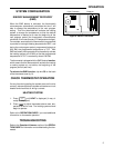
ATTACH SUBBASE TO WALL
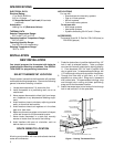
1. Remove the packing material from the thermostat.
Place the fingers of one hand on the center top and
bottom portion of the thermostat. Grasp the subbase
in the other hand on the top and bottom center, and
gently pull straight out (see fig. 2). The thermostat has
pin and socket connectors. Forcing or prying on the
thermostat will cause damage to the unit.
2. Pull wires through opening in the center of the sub-
base. DO NOT LET WIRES FALL BACK INTO
WALL.
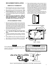
3. Connect wires beneath terminal screws on subbase
using appropriate wiring schematic (see figs. 3 through
6).
4. Place subbase over hole in wall and mark mounting
hole locations on wall using subbase as a template.
5. Move subbase out of the way. Drill mounting holes.
PULL STRAIGHT OUT
Figure 2. Removing thermostat from subbase
Mounting
Hole
Pull wires through
this opening
Connect wires under
terminal screws
Mounting
Hole
6-pin Connector
W
Expansion
Plugs
Figure 3. Subbase
Activity
Light
RH
MV
6
6. Fasten subbase loosely to wall, as shown in fig. 3,
using two mounting screws. Place a level against
bottom of subbase, adjust until level, and then tighten
screws. (Leveling is for appearance only and will not
affect thermostat operation.) If you are using existing
mounting holes, or if holes drilled are too large and do
not allow you to tighten subbase snugly, use plastic
expansion plugs to secure subbase.
7. Push excess wire into wall and plug hole with a fire-
resistant material (such as fiberglass insulation) to
prevent drafts from affecting thermostat operation.
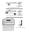
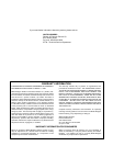
RHMV
24vAC
120vAC
Hot
Neutral
THERMOSTAT
SYSTEM
W
Figure 4. Typical Wiring Diagram for Heating Only, 2-Wire, Single Transformer Systems
TRANSFORMER
6
Heating
System
6
MV
W
RH
W
RH
Thermostat Terminal Connections
From heating system
From 24vAC transformer
All wiring diagrams are for typical systems only. Refer to
equipment manufacturers' instructions for specific sys-
tem wiring information.
To prevent electrical shock and/or equipment
damage, disconnect electrical power at the main
fuse box or circuit breaker until installation is
complete.
NOTE
CAUTION
!