


3
L
R
E
MALF
FAN ON
SYSTEM
MONITOR
SWITCH
FAN
AUTO
Heat
or Cool
FAN
AUTO
Emer
G W2
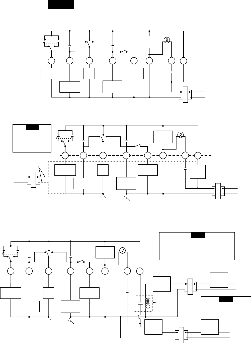
Figure 5. Typical wiring diagram for two transformer systems with safety circuits in BOTH systems
Changeover
Relay*
CYO/B
Compressor
Contactor
* Changeover Relay is energized in COOL when O/B switch is in the “O” position
Changeover Relay is energized in HEAT when O/B switch is in the “B” position
Aux/Emer
Relay
(Stage 2)
Fan
Relay
Thermostat
Control
Circuit
Emergency
Relay
TWO COMMONS MUST
BE JUMPERED TOGETHER!
24 VAC 120 VAC
HOT
NEUTRAL
THERMOSTAT
SYSTEM
HOT
NEUTRAL
120 VAC
Limit or
Safety
Switches
Limit or
Safety
Switches
Limit or
Safety
Switches
24 VAC
Limit or
Safety
Switches
COMMON
COMMON
Auxiliary
Heating
Transformer
Heat Pump Transformer
24 VAC
ACCESSORY
RELAY N.O.
CONTACT
Polarity must be observed. If the HOT side of
the second transformer is jumpered to the
COMMON side of the first transformer a short
will be made. Damage to equipment will occur
when power is restored.
NOTE
The accessory relay scheme
is required when safety
circuits exist in both systems.
NOTE
EMERGENCY
L
R
E
24 VAC
120 VAC
Hot
MALF
FAN ON
SYSTEM
MONITOR
SWITCH
FAN
AUTO
Heat
or Cool
FAN
AUTO
Emer
Neutral
THERMOSTAT
SYSTEM
G W2
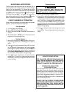
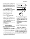
Figure 4. Typical wiring diagram for two transformer systems with NO safety circuits
TRANSFORMER
Changeover
Relay*
CYO/B
Compressor
Contactor
* Changeover Relay is energized in COOL when O/B switch is in the “O” position
Changeover Relay is energized in HEAT when O/B switch is in the “B” position
Aux/Emer
Relay
(Stage 2)
Fan
Relay
Thermostat
Control
Circuit
Emergency
Relay
Limit or
Safety
Switches
TWO COMMONS MUST
BE JUMPERED TOGETHER!
HOT
NEUTRAL
120 VAC
24 VAC
CUT AND
TAPE OFF!
If safety circuits are in
only one of the systems,
remove the transformer
of the system with NO
safety circuits.
NOTE
EMERGENCY
L
R
E
24 VAC
120 VAC
Hot
MALF
FAN ON
EMERGENCY
SYSTEM
MONITOR
SWITCH
FAN
AUTO
Heat
or Cool
FAN
AUTO
Emer
Neutral
THERMOSTAT
SYSTEM
G W2
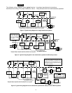
Figure 3. Typical wiring diagram for single transformer systems
TRANSFORMER
Changeover
Relay*
CYO/B
Compressor
Contactor
* Changeover Relay is energized in COOL when O/B switch is in the “O” position
Changeover Relay is energized in HEAT when O/B switch is in the “B” position
Aux/Emer
Relay
(Stage 2)
Fan
Relay
Thermostat
Control
Circuit
Emergency
Relay
NOTE
The following wiring diagrams show typical terminal
identification and wiring. For proper installation, refer to
the original manufacturer's instructions.
Relay contacts shown are thermostatically operated.