


2
INSTALLATION
REMOVE OLD THERMOSTAT
1. Shut off electricity at the main fuse box until installation
is complete. Ensure that electrical power is discon-
nected.
2. Remove the front cover of the old thermostat. With
wires still attached, remove wall plate from the wall.
If the old thermostat has a wall mounting plate, remove
the thermostat and the wall mounting plate as an
assembly.
3. Identify each wire attached to the old thermostat
using the labels enclosed with the new thermostat.
4. Disconnect the wires from old thermostat one at a time.
DO NOT LET WIRES FALL BACK INTO THE WALL.
5. Install new thermostat using the following procedures.
ATTACH THERMOSTAT BASE TO WALL
1. Remove the packing material from the thermostat.
2. If necessary, cut the non-electric heat jumper (see
NON-ELECTRIC HEAT SYSTEMS). Check the set-
ting of the O/B switch (see O/B TERMINAL SWITCH
SELECTION).
3. If you want to review the thermostat features before
mounting the thermostat on the wall, see ARMCHAIR
DEMONSTRATION.
4. Gently pull the thermostat cover straight off the base.
Forcing or prying on the thermostat will cause damage
to the unit.
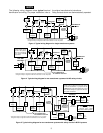
5. Check that the system switch is in the OFF position.
Connect wires beneath terminal screws on base using
appropriate wiring schematic (see figs. 3 through 5).
6. Place base over hole in wall and mark mounting hole
locations on wall using base as a template.
7. Move base out of the way. Drill mounting holes.
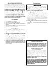
8. Fasten base loosely to wall, as shown in fig. 2, using
two mounting screws. Place a level against bottom of
base, adjust until level, and then tighten screws. (Lev-
eling is for appearance only and will not affect thermo-
stat operation.) If you are using existing mounting
holes, or if holes drilled are too large and do not allow
you to tighten base snugly, use plastic screw anchors
to secure subbase.
9. Push excess wire into wall and plug hole with a fire-
resistant material (such as fiberglass insulation) to
prevent drafts from affecting thermostat operation.
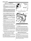
NON-ELECTRIC HEAT SYSTEMS
Read the following information before clipping the non-
electric heat jumper. If you are unsure of your application,
contact a qualified serviceperson.
If your emergency or auxiliary system is non-electric (gas,
oil, etc.) and will energize the blower, then jumper, W904,
on the back of the thermostat base must be cut (see fig. 1).
If your emergency or auxiliary heat system is electric and
requires that the thermostat energize the fan circuit, do
not cut jumper W904.
O/B TERMINAL SWITCH SELECTION
The O/B switch on this thermostat is factory set to the “O”
position. This will accommodate the majority of heat pump
applications, which require the changeover relay to be
energized in COOL. If the thermostat you are replacing or
the heat pump being installed with this thermostat require
the “B” terminal, to energize the changeover relay in
HEAT, the O/B switch must be moved to the “B” position.
ARMCHAIR DEMONSTRATION
Armchair Demonstration is a unique feature that allows
you to review your thermostat features before being
mounted on the wall.
If you wish an Armchair Demonstration of your thermo-
stat, temporarily hold a new 9-volt battery against the
wires in the battery cutout on the back of the thermostat
base for approximately 45 seconds. This will provide a
charge that will last approximately 30 to 45 minutes to
allow the thermostat to be observed.
Figure 1. Back of thermostat base
W904
CUT FOR
NON-ELECTRIC
AUX.
O
B
BATTERY CUTOUT FOR
ARMCHAIR DEMONSTRATION
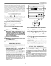
Figure 2. Thermostat base
AUTO
FAN ON
COOL
OFF
HEAT
EMER
Reset Button
Mounting
holes
Screw anchors
L
E
Y
W2
O/B
R
G
C