


3
RH
Y
24 VAC
120 VAC
Hot
Neutral
THERMOSTAT
SYSTEM
G W
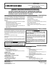
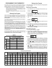
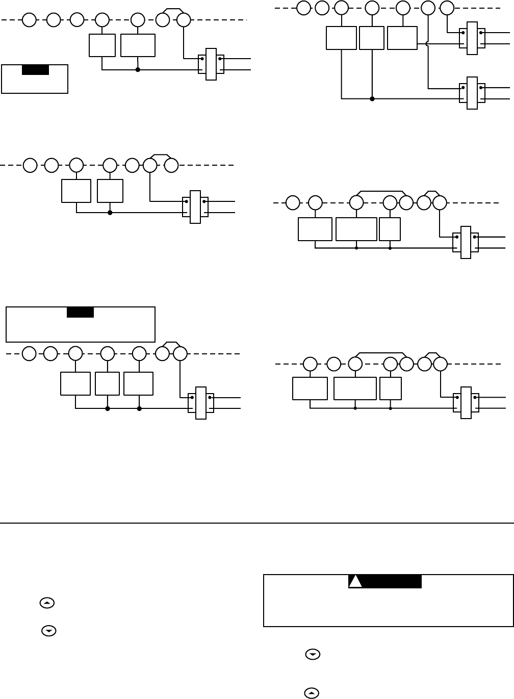
Figure 5. Typical wiring diagram for
heat/cool, 5-wire, two-transformer systems
HEATING TRANSFORMER
(Class II Current Limited)
Heating
System
Fan
Relay
Cooling
System
RC
24 VAC
120 VAC
Hot
Neutral
COOLING TRANSFORMER
(Class II Current Limited)
OB
RH
Y
24 VAC
120 VAC
Hot
Neutral
THERMOSTAT
SYSTEM
G W
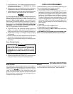
Figure 4. Typical wiring diagram for
heat/cool, 4-wire, single transformer systems
Heating
System
Fan
Relay
Cooling
System
RC
JUMPER
WIRE
OB
RED jumper wire (provided with thermostat) must be
connected between thermostat RH and RC terminals
for proper thermostat operation with this system.
NOTE
TRANSFORMER
(Class II Current Limited)
RH
24 VAC
120 VAC
Hot
Neutral
THERMOSTAT
SYSTEM
G W
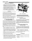
Figure 2. Typical wiring diagram for
heat only, 3-wire, single transformer systems
TRANSFORMER
(Class II Current Limited)
Heating
System
Fan
Relay
Y
RC
JUMPER
WIRE
OB
For 2-wire Heat only,
attach to RH and W
NOTE
RH
Y
24 VAC
120 VAC
Hot
Neutral
THERMOSTAT
SYSTEM
G W
Figure 7. Typical wiring diagram for heat pump
with reversing valve energized in HEAT
Reversing
Valve*
RCOB
JUMPER
WIRE
Compressor
Contactor
JUMPER
WIRE
* Reversing valve is energized when the
system switch is in the HEAT position
Fan
Relay
TRANSFORMER
(Class II Current Limited)
RH
Y
24 VAC
120 VAC
Hot
Neutral
THERMOSTAT
SYSTEM
G W
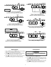
Figure 3. Typical wiring diagram for
cool only, 3-wire, single transformer systems
Cooling
System
Fan
Relay
RCOB
JUMPER
WIRE
TRANSFORMER
(Class II Current Limited)
RH
Y
24 VAC
120 VAC
Hot
Neutral
THERMOSTAT
SYSTEM
G W
Figure 6. Typical wiring diagram for heat pump
with reversing valve energized in COOL
Reversing
Valve*
RCOB
JUMPER
WIRE
Compressor
Contactor
JUMPER
WIRE
* Reversing valve is energized when the
system switch is in the COOL position
Fan
Relay
TRANSFORMER
(Class II Current Limited)
Heating System
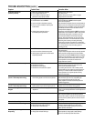
1. Move SYSTEM switch to HEAT position. If the heating
system has a standing pilot, be sure to light it.
2. Press to adjust thermostat setting above room tempera-
ture. The heating system should begin to operate.
3. Press
to adjust temperature setting below room tem-
perature. The heating system should stop operating.
CAUTION
!
Cooling System
To prevent compressor and/or property damage, if the
outdoor temperature is below 50°F, DO NOT operate
the cooling system.
1. Move SYSTEM switch to COOL position.
2. Press
to adjust thermostat setting below room tem-
perature. The blower should come on immediately on high
speed, followed by cold air circulation
3. Press to adjust temperature setting above room tem-
perature. The cooling system should stop operating.