


2
WIRING CONNECTIONSWIRING CONNECTIONS
WIRING CONNECTIONSWIRING CONNECTIONS
WIRING CONNECTIONS
Refer to equipment manufacturers' instructions for specific
system wiring information. After wiring, see CONFIGURA-
TION section for proper thermostat configuration.
Refer to
37-684337-6843
37-684337-6843
37-6843 for 1F83-0471/1F85-0471 wiring diagram
specifications.
WARNING
!
Thermostat installation and all components of theThermostat installation and all components of the
Thermostat installation and all components of theThermostat installation and all components of the
Thermostat installation and all components of the
control system shall conform to Class II circuits per thecontrol system shall conform to Class II circuits per the
control system shall conform to Class II circuits per thecontrol system shall conform to Class II circuits per the
control system shall conform to Class II circuits per the
NEC code.NEC code.
NEC code.NEC code.
NEC code.
INSTINST
INSTINST
INST
ALLAALLA
ALLAALLA
ALLA
TIONTION
TIONTION
TION
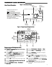
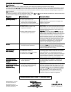
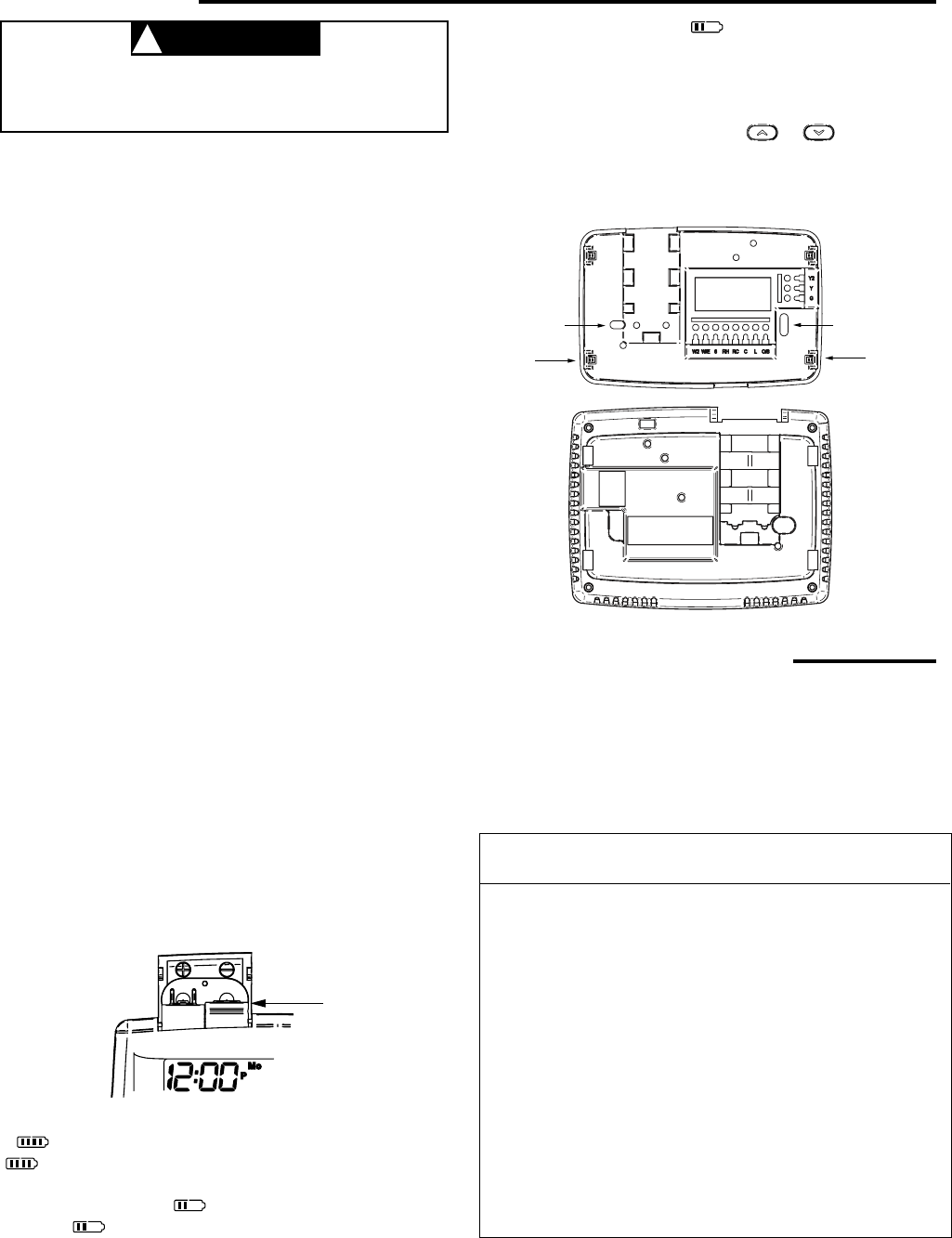
Figure 2 – Thermostat base and rear view of thermostatFigure 2 – Thermostat base and rear view of thermostat
Figure 2 – Thermostat base and rear view of thermostatFigure 2 – Thermostat base and rear view of thermostat
Figure 2 – Thermostat base and rear view of thermostat
RR
RR
R
emoemo
emoemo
emo
vv
vv
v
e Old e Old
e Old e Old
e Old
TT
TT
T
herher
herher
her
mostamosta
mostamosta
mosta
tt
tt
t
A standard heat/cool thermostat consists of three basic parts:
1. The cover, which may be either a snap-on or hinge type.
2. The base, which is removed by loosening all captive screws.
3. The switching subbase, which is removed by unscrewing
the mounting screws that hold it on the wall or adapter
plate.
BefBef
BefBef
Bef
oror
oror
or
e re r
e re r
e r
emoemo
emoemo
emo
ving wirving wir
ving wirving wir
ving wir
es fres fr
es fres fr
es fr
om old therom old ther
om old therom old ther
om old ther
mostamosta
mostamosta
mosta
t,t,
t,t,
t,
lala
lala
la
bel eacbel eac
bel eacbel eac
bel eac
h wirh wir
h wirh wir
h wir
e with the tere with the ter
e with the tere with the ter
e with the ter
minal designaminal designa
minal designaminal designa
minal designa
tion frtion fr
tion frtion fr
tion fr
omom
omom
om
ww
ww
w
hichic
hichic
hic
h it wh it w
h it wh it w
h it w
as aas a
as aas a
as a
ttacttac
ttacttac
ttac
hedhed
hedhed
hed. Disconnect the wires from the old
thermostat one at a time.
Do not let wirDo not let wir
Do not let wirDo not let wir
Do not let wir
es fes f
es fes f
es f
all bacall bac
all bacall bac
all bac
k intok into
k intok into
k into
the wthe w
the wthe w
the w
allall
allall
all.
Installing NeInstalling Ne
Installing NeInstalling Ne
Installing Ne
w w
w w
w
TT
TT
T
herher
herher
her
mostamosta
mostamosta
mosta
tt
tt
t
1. Pull the thermostat body off the thermostat base. Forcing
or prying on the thermostat will cause damage to the unit.
2. Place base over hole in wall and mark mounting hole
locations on wall using base as a template.
3. Move base out of the way. Drill mounting holes. If you
are using existing mounting holes and the holes drilled
are too large and do not allow you to tighten base snug-
ly, use plastic screw anchors to secure the base.
4. Fasten base snugly to wall using mounting holes shown
in Figure 2 and two mounting screws. Leveling is for
appearance only and will not affect thermostat operation.
5. Connect wires to terminal block on base.
6. Push excess wire into wall and plug hole with a fire re-
sistant material (such as fiberglass insulation) to prevent
drafts from affecting thermostat operation.
7. Carefully line the thermostat up with the base and snap
into place.
TT
TT
T
erer
erer
er
minalminal
minalminal
minal
DesignaDesigna
DesignaDesigna
Designa
tiontion
tiontion
tion
DescriptionDescription
DescriptionDescription
Description
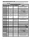
L . . . . . . Heat pump malfunction indicator for systems
with malfunction connection
O . . . . . .Changeover valve for heat pump energized
constantly in cooling
B . . . . . . Changeover valve for heat pump energized
constantly in heating
Y . . . . . . Compressor Relay
Y2 . . . . . . 2nd Stage Compressor
W/E . . . . .Heat Relay/Emergency Heat Relay (Stage 1)
W2 . . . . .2nd Stage Heat (3rd Stage Heat in HP 2)
G . . . . . .Fan Relay
RH . . . . . Power for Heating
RC . . . . .Power for Cooling
C . . . . . .Common wire from secondary side of cooling
system transformer or heat only system transformer
6 . . . . . .3 Wire Zone Valve – Energized when no call
for Heat
TERMINTERMIN
TERMINTERMIN
TERMIN
AL DESIGNAL DESIGN
AL DESIGNAL DESIGN
AL DESIGN
AA
AA
A
TION DESCRIPTIONSTION DESCRIPTIONS
TION DESCRIPTIONSTION DESCRIPTIONS
TION DESCRIPTIONS
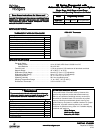
“AA” Alkaline Batteries
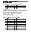
Figure 1 – Battery door shown openFigure 1 – Battery door shown open
Figure 1 – Battery door shown openFigure 1 – Battery door shown open
Figure 1 – Battery door shown open
BaBa
BaBa
Ba
tteriestteries
tteriestteries
tteries
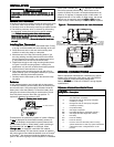
2 "AA" alkaline batteries are included with the thermostat.
To install the batteries, pull the battery door as shown by the
arrow and lift open. Using the polarity indicated inside the
battery door, insert the batteries. To close the battery door,
swing the door down while pulling in the direction of arrow.
Once fully down, snap the door back into position. To
replace the batteries, set system to OFF.
Thermostat can be powered by system AC power or Battery.
If
is displayed, the thermostat is battery powered. If
is not displayed, thermostat is system powered with
optional battery back-up. When battery power remaining is
approximately half, the
will be displayed. When
"
ChangChang
ChangChang
Chang
ee
ee
e " is displayed, install fresh “AA” alkaline
batteries immediately. For best results, replace all batteries
with new premium brand alkaline batteries such as Duracell
®
or Energizer
®
. We recommend replacing batteries every 2
years. If the home is going to be unoccupied for an extended
Mounting
Hole
Mounting
Hole
Place Level
across
Mounting Tabs
(for appearance only)
Place Level
across
Mounting Tabs
(for appearance only)
period (over 3 months) and is displayed, the batteries
should be replaced before leaving. When less than two
months of battery life remain, the setpoint temperature will
offset by 10 degrees (10 degrees cooler in Heat mode / 10
degrees warmer in Cool mode). If offset occurs, the normal
setpoint can be manually reset with
or . Another
offset will occur within two days if batteries are not replaced.