


4
CAUTION
!
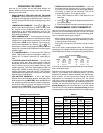
CHECK THERMOSTAT OPERATION
If at any time during testing your system does not operate
properly, contact a qualified serviceperson.
Fan Operation
If your system does not have a G terminal connection, skip to
Heating System.
1. Turn on power to the system.
2. Move FAN switch to ON position. The blower should begin
to operate.
3. Move FAN switch to AUTO position. The blower should stop
immediately.
Heating System
1. Move SYSTEM switch to HEAT position. If the heating
system has a standing pilot, be sure to light it.
2. Press to adjust thermostat setting above room tempera-
ture. The heating system should begin to operate.
3. Press
to adjust temperature setting below room tempera-
ture. The heating system should stop operating.
Cooling System
To prevent compressor and/or property damage, if the
outdoor temperature is below 50°F, DO NOT operate
the cooling system.
1. Move SYSTEM switch to COOL position.
2. Press to adjust thermostat setting below room tempera-
ture. The blower should come on immediately on high speed,
followed by cold air circulation
3. Press to adjust temperature setting above room tem-
perature. The cooling system should stop operating.
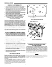
Before you begin programming your thermostat, you should be
familiar with its features and with the display and the location and
operation of the thermostat buttons. Your thermostat consists of
two parts: the thermostat cover and the base. To remove the
cover, gently pull it straight out from the base. To replace the
cover, line up the cover with the base and press gently until the
cover snaps onto the base.
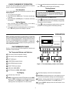
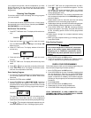
THE THERMOSTAT BASE
See fig. 11 for the location of the following buttons, switches and
indicators on the thermostat.
The Thermostat Buttons and Switches
1
(Red arrow) Raises temperature setting.
2
(Blue arrow) Lowers temperature setting.
3
SET TIME button.
4
VIEW PRGM (program) button.
5
RUN PRGM (program) button.
6
HOLD TEMPerature button.
7
FAN switch (ON, AUTO).
8
SYSTEM switch (COOL, OFF, HEAT).
The Display
9
Indicates day of the week.
10
HEAT is displayed when the SYSTEM switch is in the HEAT
position. COOL is displayed (non-flashing) when the SYS-
TEM switch is in the COOL position. COOL is displayed
(flashing) when the compressor is in lockout mode.
OPERATION
11
Alternately displays current time and temperature.
12
BATTERY is displayed when the 3 “AA” batteries are low
and should be replaced. Nothing else will be displayed.
13
Displays currently programmed set temperature (this is
blank when SYSTEM switch is in the OFF position).
14
The word HOLD is displayed when the thermostat is in the
HOLD mode.
Figure 11. Thermostat display, buttons, and switches
SU
HOLD
SA
COOL
BATTERY
AM
MO TU WE TH FR
HEAT
9 910
1012 1113 14
11
AUTOSET TIME VIEW PRGM RUN PRGM HOLD TEMP FAN ON COOL OFF HEAT
3
2
1
4 5 6 7 8
WHITE-RODGERS