


3
RH
Y
24 VAC
120 VAC
Hot
Neutral
THERMOSTAT
SYSTEM
G W
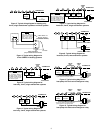
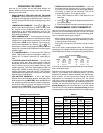
Figure 10. Typical wiring diagram for
heat pump with heat active changeover relay
TRANSFORMER
Changeover
Relay*
RCOB
JUMPER
WIRE
Compressor
Contactor
JUMPER
WIRE
* Changeover Relay is energized when the
system switch is in the HEAT position
Fan
Relay
RH
Y
24 VAC
120 VAC
Hot
Neutral
THERMOSTAT
SYSTEM
G W
Figure 7. Typical wiring diagram for
heat/cool, 4-wire, single transformer systems
TRANSFORMER
Heating
System
Fan
Relay
Cooling
System
RC
JUMPER
WIRE
RED jumper wire (provided
with thermostat) must be
connected between thermo-
stat's RH and RC terminals
for proper thermostat oper-
ation with this system.
NOTE
OB
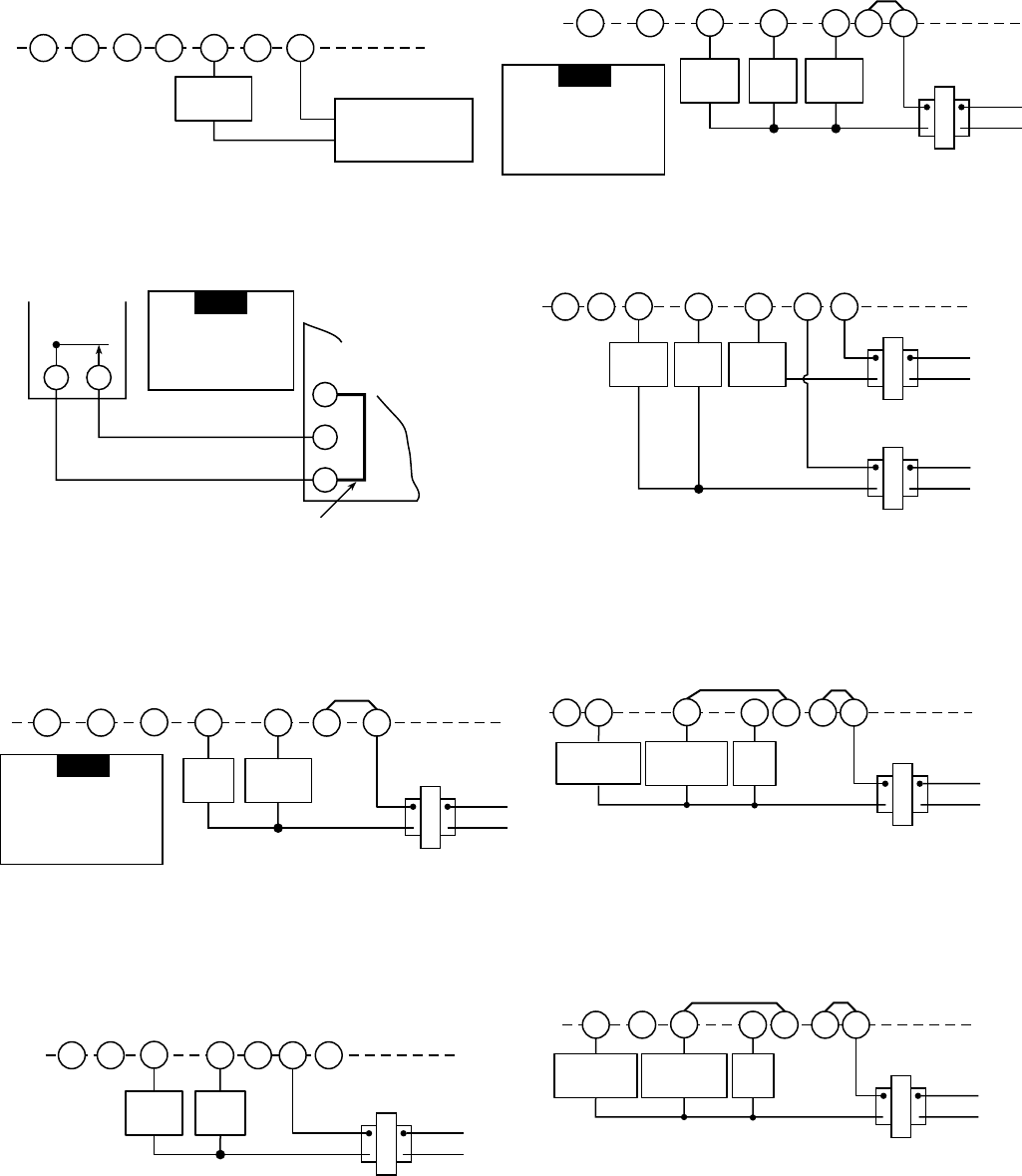
RH
Y
24 VAC
120 VAC
Hot
Neutral
TRANSFORMER
THERMOSTAT
SYSTEM
G W
Figure 6. Typical wiring diagram for
cool only, 3-wire, single transformer systems
Cooling
System
Fan
Relay
RCOB
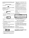
RW
B
W
R
Thermostat
3-wire Series 10
Primary Control
(located at furnace)
Add jumper wire
(not provided with thermostat)
Figure 4. Typical wiring diagram for
3-wire SERIES 10 heating systems
Furnace
Jumper wire must be
added between R and B
terminals on the primary
control (jumper wire not
provided with thermostat.
NOTE
RH
Y
24 VAC
120 VAC
Hot
Neutral
THERMOSTAT
SYSTEM
G W
Figure 8. Typical wiring diagram for
heat/cool, 5-wire, two-transformer systems
HEATING TRANSFORMER
Heating
System
Fan
Relay
Cooling
System
RC
24 VAC
120 VAC
Hot
Neutral
COOLING TRANSFORMER
OB
RH
Y
24 VAC
120 VAC
Hot
Neutral
THERMOSTAT
SYSTEM
G W
Figure 5. Typical wiring diagram for
heat only, 3-wire, single transformer systems
TRANSFORMER
Heating
System
Fan
Relay
Y
RC
JUMPER
WIRE
RED jumper wire (provided
with thermostat) must be
connected between thermo-
stat's RH and RC terminals
for proper thermostat oper-
ation with this system.
NOTE
OB
RH
Y
THERMOSTAT
SYSTEM
G W
Figure 3. Typical wiring diagram for heating only,
2-wire, single transformer systems or millivolt systems
Heating
System
RCOB
24 VAC Transformer
or
Thermopile
RH
Y
24 VAC
120 VAC
Hot
Neutral
THERMOSTAT
SYSTEM
G W
Figure 9. Typical wiring diagram for
heat pump with cool active changeover relay
TRANSFORMER
Changeover
Relay*
RCOB
JUMPER
WIRE
Compressor
Contactor
JUMPER
WIRE
* Changeover relay is energized when the
system switch is in the COOL position
Fan
Relay