


50 60 70 80 90
EMER AUX
70
FAN
AUTO
ON
COOL
OFF
HEAT
EMER
SYSTEM
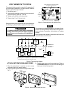
Figure 6. Thermostat with door open
Anticipation
Reference
Number
Approx.
Temperature
Differential*
10
14
16
30
0.8°F
1.1°F
1.3°F
2.4°F
Anticipation
Reference
Number
Approx.
Temperature
Differential*
10
14
16
30
0.3°F
0.4°F
0.5°F
0.9°F
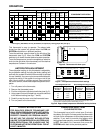
Figure 8. Approximate temperature differential and cycle times
First Stage Heat & Cool
Second Stage & Emergency Heat
* These numbers are approximate and represent thermostat operation with a
typical system. Actual temperature differentials may vary.
OPERATION
This thermostat is easy to operate. The above table
shows how the system will operate when the FAN and
SYSTEM switches are in different positions.
To set the switches, open the door on the left side of the
thermostat (see fig 6). Move the FAN and SYSTEM
switches up or down to select desired system operation.
To set the temperature, move the temperature selection
knob (on the right side of the thermostat) until the desired
temperature is shown in the window.
ANTICIPATION ADJUSTMENT
The anticipation setting on this thermostat is adjustable.
Any anticipation setting (including the factory setting) will
work with any system for which this thermostat is intended
for use. However, the user may be more comfortable with
a particular setting. If the system is turning on and off too
often (short cycles) or not often enough (long cycles) for
the user’s comfort, follow these steps to adjust the antici-
pation.
1. Turn off power to the thermostat.
2. Remove the thermostat cover.
3. Find the anticipation adjustment switches (see fig. 3).
4. Using a pencil or small screwdriver, move the switches
to the desired setting (see figs. 7 and 8).
5. Carefully snap the cover onto the thermostat base.
6. Turn on power to the thermostat.
LOCKOUT BYPASS OPTION
FOR QUALIFIED SERVICE TECHNICIANS’ USE
ONLY. OPERATORS SHOULD NOT USE THIS FEA-
TURE DUE TO POSSIBILITY OF EQUIPMENT OR
PROPERTY DAMAGE, OR PERSONAL INJURY.
DO NOT USE THE LOCKOUT BYPASS OPTION
UNLESS THE COMPRESSOR OIL HEATERS HAVE
BEEN OPERATIONAL FOR 6 HOURS AND THE
SYSTEM HAS NOT BEEN OPERATIONAL FOR AT
LEAST 5 MINUTES.
COMPRESSOR SHORT TERM
CYCLE PROTECTION
This thermostat has a built-in short term (5-minute)
time delay. During this 5-minute period, the thermostat
will lock out the compressor to allow head pressure to
stabilize. If you want to override this feature while
testing thermostat operation, move the SYSTEM switch
to OFF. Wait about 6 to 8 seconds, then move the
SYSTEM switch back to the previous position.
SWITCH POSITIONS SYSTEM FUNCTION
COMPONENT OPERATION
Aux
Heat
Relay
Rev
Valve
(O)
Fan
Relay
Compr.
Contact
Emer
LightAuto On Cool Off Heat Emer
FAN SYSTEM
No heat - no cool - no fan - no lights
Heating Mode: stage 1 calling. Fan relay,
compressor contactor, and reversing valve (B)
energized by thermostat.
Heating Mode: both stages calling. Fan relay,
compressor contactor, reversing valve (B),
and auxiliary heat relay are energized.
Emergency Heat Mode: aux heat, fan relay
*
,
and reversing valve (B) are energized.
Compressor locked out.
Cooling Mode: Fan relay, compressor
contactor and reversing valve (O) energized.
Fan On: Energizes fan relay regardless
of system switch position.
Indicates switch position on thermostat subbase and system function in operation.
Rev
Valve
(B)
Aux.
Light
* In Emergency Heat Mode, fan may be disabled, if required, by cutting jumper W7 (see fig 3).
12
OFF
Antic.=10*
Shorter
Cycles
Longer
Cycles
12
OFF
Antic.=14*
(Factory setting)
12
OFF
Antic.=16*
12
OFF
Antic.=30*
* These numbers represent different anticipation settings. See fig. 8 for
further information.
Figure 7. Anticipation selection switch settings