


G
O
Y
B
1
2
O
F
F
G
O
Y
B
1
2
O
F
F
70
69
68
67
66
65
64
62
60
55
50
45
40
71
72
73
74
75
76
77
78
79
80
81
82
83
84
86
88
90
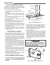
Setpoint
Knob
Setpoint
Switch
Figure 5. Attach setpoint knob and cover
A
C
50 60 70 80 90
EMER
AUX
B
70
69
68
67
66
65
64
62
60
55
50
45
40
71
72
73
74
75
76
77
78
79
80
81
82
83
84
86
88
90
G
O
Y
B
1
2
O
F
F
70
69
68
67
66
65
64
62
60
55
50
45
40
71
72
73
74
75
76
77
78
79
80
81
82
83
84
86
88
90
L
C R
GO
Reversing
Valve**
Fan
Relay
Auxiliary
Heat
Relay
Thermostat
Control
Circuit
Compressor
Contactor
24 VAC
120 VAC
Hot
Neutral
THERMOSTAT
SYSTEM
Y
W
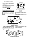
Figure 4. Typical wiring diagram
TRANSFORMER
Malfunction
Light
†
Malfunction
Switch
* Reversing valve is energized when the System Switch is in the HEAT position
** Reversing valve is energized when the System Switch is in the COOL position
†
Emergency light shown wired to malfunction circuit
B
Reversing
Valve*
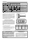
Figure 3. Thermostat base with typical wiring
Pull wires through this opening
Setpoint switch
(without knob)
Insert stripped wires into terminal blocks,
then tighten terminal screws.
G
O
Y
B
R
Aux. Light
Emer. Heat
Light
WLC
1
2
O
F
F
Anticipation
Selection
Switches
W7
See
System
Function
Table
WIRE THERMOSTAT TO SYSTEM
For best electrical connection, use solid 18 gauge wire. If
you must use stranded wire, tin the wires with solder to
insure a good electrical connection.
1. Strip wires back
1
⁄
4
”.
2. Using needle-nose pliers, insert wire into correct termi-
nal block opening (see figs. 3 and 4).
3. Tighten terminal block connector screw.
4. Repeat steps 2 and 3 for each wire.
Some applications may require that the fan be disabled in
the Emergency Mode. Refer to System Function Table.
To prevent electrical shock and/or equipment
damage, disconnect electrical power to system,
at main fuse or circuit breaker, until installation is
complete.
This typical wiring diagram shows only the terminal iden-
tification and wiring hookup. Always refer to wiring instruc-
tions provided by equipment manufacturer for system
hookup.
All wiring should be installed in accordance with local and
national codes and ordinances.
NOTE
ATTACH SETPOINT KNOB AND COVER
1. After thermostat base is mounted on wall, remove
cardboard insert from setpoint switch.
2. Carefully press setpoint knob onto setpoint switch (see
fig. 5).
3. Carefully snap cover onto thermostat base. Refer to
the OPERATION section for instructions on setting the
thermostat for desired operation.
CAUTION
!
NOTE