


5
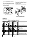
The stage 2 heat anticipator is located on the thermostat
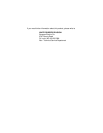
base. Adjust the anticipator by turning the lever until the
pointer is set on the correct anticipator setting determined
above (see fig. 6). If additional adjustments are neces-
sary, they may be made as follows (adjust the anticipator
1
⁄2 division at a time; for example, from 0.6 to 0.55).
1. If shorter heating cycles are desired, set the anticipa-
tor to a slightly lower setting.
2. If longer heating cycles are desired, set the anticipa-
tor to a slightly higher setting.
ADJUSTING STAGE 2 HEAT ANTICIPATOR
This thermostat is equipped with two anticipators. The
anticipator for stage 1 heat and cool is fixed and does not
require any adjustments. The stage 2 anticipator is adjust-
able and must be set to the current draw of the component
it is controlling.
To determine the correct stage 2 anticipator setting,
measure the current draw of the stage 2 (auxiliary heat)
relay. You may use the following procedure to determine
current draw.
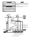
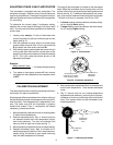
1. Loosely wrap exactly 10 coils of thermostat wire
around the jaws of a split-jaw induction-type current
meter (see fig. 5).
2. With the subbase correctly wired to the heat pump
system, attach one end of the 10-turn coil to terminal
R and attach the other end to terminal W1.
3. With the heat pump system power on, center the coil
on the meter jaws and read the current draw of the
stage 2 heat relay on the meter and divide the reading
by 10. This is the value that should be set on the
adjustable anticipator.
Example:
Meter reads 6.0 amp
10 turns of wire
4. Turn power to heat pump system off, then remove
coil leads from the subbase and move system switch
to OFF.
= 0.6 amp anticipator setting
10 turns
of wire
Split jaw
current meter
Figure 5. Current meter
.18
L
O
N
G
E
R
C
Y
S
.25
.3
.4
.2
.15
1.0
.8
.6
.5
Arrow points to the
matched current rating
of the primary control
Move this lever to
adjust heat
anticipator
Figure 6. Anticipator adjustment
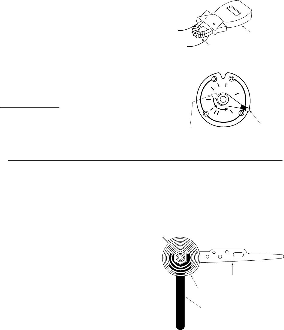
Bimetal
7/32" Calibration
Wrench
Temperature
Adjustment
Lever
Figure 7. Calibrating thermostat
CALIBRATION ADJUSTMENT
This thermostat has been carefully adjusted at the factory
and should not require recalibration.
A few degrees difference between the indicator setting of
the thermostat and actual room temperature is not consid-
ered important. If the disagreement is appreciable, how-
ever, first make sure that the thermostat is properly
located and leveled. Then, if recalibration still seems
necessary, proceed as follows:
1. Move temperature adjustment lever to a setting about
5° above room temperature.
2. Remove thermostat cover. Slip
7
⁄32” wrench onto hex
nut beneath bimetal and hold temperature adjust-
ment lever stationary. Turn hex nut clockwise until
mercury shifts to right end of tube (see fig. 7).
3. Move temperature adjustment lever to lowest setting.
4. Replace thermostat cover. Wait 10 minutes for bi-
metal temperature to stabilize. Don’t stand near ther-
mostat during this period as your breath and body
heat will affect temperature of bimetal.
5. Move temperature adjustment lever to correspond to
actual room temperature. Then remove thermostat
cover.
6. Slip
7
⁄32” wrench onto hex nut, holding temperature
adjustment lever stationary, and turn hex nut counter-
clockwise until mercury just barely shifts to left end of
tube. Then replace cover and set thermostat to de-
sired temperature.