


4
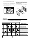
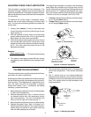
ATTACH THERMOSTAT TO SUBBASE
1. Remove cover from thermostat base by gripping the
base in one hand and with the fingers of the other
hand, pull lightly at the top or bottom of the cover.
2. Carefully remove the shipping protective packing
from the mercury switches.
3. Attach thermostat base to subbase. Be sure that all
captive screws are tightened snugly, because they
serve as electrical connections between thermostat
and subbase (see fig. 4).
4. Snap cover onto thermostat and set temperature
lever to desired setpoint. Turn on electrical power.
OPERATION &
MAINTENANCE
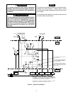
The chart below shows the how the system functions when
the system and fan switches are in various positions.
G
O
B
B
B
B
B
O
G
Compr.
Contact
SUBBASE SWITCH POSITIONS SYSTEM FUNCTION
COMPONENT OPERATION
Emer
Heat
Relay
Rev
Valve
Fan
RelayAuto On Cool Off Heat Emer
FAN SYSTEM
No heat - no cool - no fan - no lights
Heat Mode: stage 1 calling. Fan relay and com-
pressor contactor energized by thermostat.
Heat Mode: both stages calling. Fan relay, com-
pressor contactor, and auxiliary heat relay are
energized. Aux. light on.
Emergency Heat Mode: stage 1 calling. Emergency
heat relays energized. Compressor locked out at
thermostat. Emer. light on.
Emergency Heat Mode: both stages calling. Emer-
gency and auxiliary heat relays energized. Compres-
sor locked out at thermostat. Emer. and aux. lights on.
Cool Mode: Compressor contactor and fan relay
energized.
Indicates switch position on thermostat subbase
and system function at those switch positions.
Aux
Heat
Relay
Emer
Light
Aux
Light
G
Fan relay energized. Fan runs continuously,
regardless of system switch position.
When check light is wired to a malfunction switch in
the heat pump system, check light will come on when
the malfunction switch contacts close, regardless of
system switch position.
Reversing valve energized if connected to B terminal.
Reversing valve energized if connected to the O terminal.
See fig. 2 (fan caution)
OFF
AUTO
ON
FAN SYSTEM
COOL HEAT
G
R
Y
Figure 3. Thermostat subbase
EMER.
EMER
HEAT
W2
Mounting screw
KEEP THIS AREA
CLEAR OF WIRES!
Hole
in wall
Mounting screw
CHECK
LIGHT
AUX
HEAT
OLX1
B
E
Figure 4. Attach thermostat to subbase
Cover
Thermostat
Subbase
Captive terminal
screws
Captive terminal
screws
Mounting
screws
50
60
70
80
60
50
70
80
90
90
OFF
FAN
AUTO ON
SYSTEM
COOL HEAT
LIGHT
CHECK
HEAT
EMER
HEAT
AUX