


2
SPECIFICATIONS
ELECTRICAL DATA
Switch Rating: 24vAC (30vAC max.)
Adjustable Heat Anticipator - 0.15 to 1.2 Amps
Switch Action: SPST - Sealed mercury switch
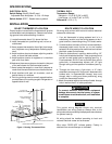
SELECT THERMOSTAT LOCATION
Proper location insures that the thermostat will provide
a comfortable home temperature. Observe the follow-
ing general rules when selecting a location.
1. Locate thermostat about 5 ft. above the floor.
2. Install thermostat on a partitioning wall, not on an
outside wall.
3. Never expose thermostat to direct light from lamps,
sun, fireplaces or any temperature radiating equip-
ment.
4. Avoid locations close to windows, adjoining outside
walls, or doors that lead outside.
5. Avoid locations close to air registers or in the direct
path of air from them.
6. Make sure there are no pipes or duct work in that part
of the wall chosen for the thermostat location.
7. Never locate thermostat in a room that is warmer or
cooler than the rest of the home, such as the kitchen.
8. Avoid locations with poor air circulation, such as
behind doors or in alcoves.
9. The living or dining room is normally a good location,
provided there is no cooking range or refrigerator on
opposite side of wall.
THERMAL DATA
Temperature Range:
Standard = 10° to 32°C (50° to 90°F)
Low Range = 4° to 24°C (40° to 75°F)
Differential: 1/2°C (1°F)
INSTALLATION
ROUTE WIRES TO LOCATION
All wiring must conform with local and national electrical
codes and ordinances.
1. If an old thermostat is being replaced and is in a
satisfactory location, and the wiring appears to be in
good condition, use existing wiring. If in doubt, rewire.
2. If a new location is chosen or if this is a new installation,
thermostat cable must first be run to the location
selected. All wiring must conform with local and national
electrical codes and ordinaces.
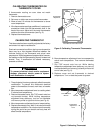
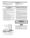
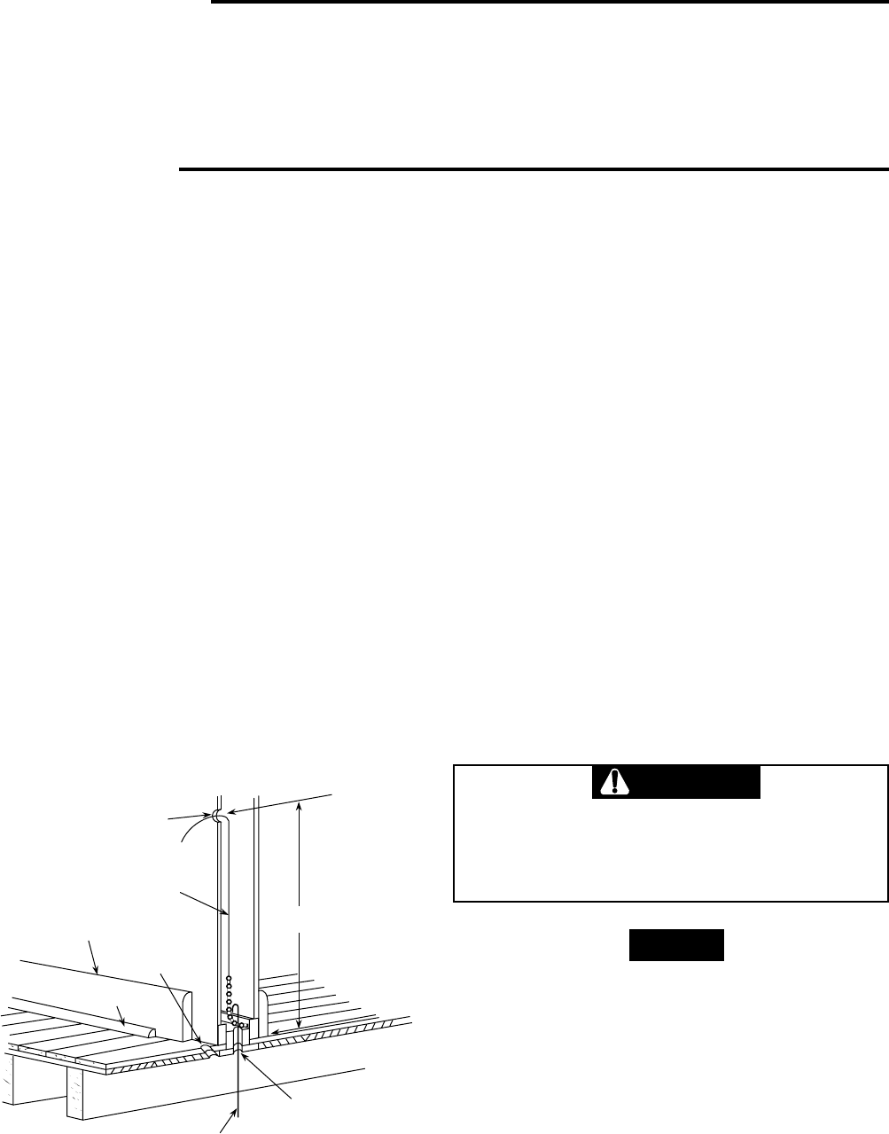
3. Probe for obstructions in partition before drilling 1/2"
hole in wall at selected location. Take up quarter round
and drill a small guide hole for sighting (see Fig. 1).
From basement, drill 3/4" hole in partition floor next to
guide hole. In basementless houses, drill 1/2" hole
through ceiling and into partition from above (see Fig.
1).
4. Through this hole drop a light chain, or 6" chain
attached to a strong cord. Snag cord in basement with
hooked wire. In basementless houses, drop cord
through hole in ceiling and down partitioning; snag
cord at the thermostat location.
5. Attach thermostat cable to cord and pull cable through
hole in wall so that 6" of cable protrudes.
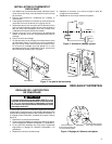
CAUTION
To prevent electrical shock and/or equipment
damage, disconnect electrical power to system,
at main fuse or circuit breaker box, until installation
is complete.
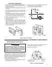
NOTE
This typical wiring diagram shows only terminal
identification and wiring hook-up. Always refer to the
wiring instructions provided by the equipment manufacturer
for system hook-up.
All wiring should be installed according to local and
national electrical codes and ordinances.
Wire colour DOES NOT indicate polarity. Polarity is
obtained from an oscilloscope or voltmeter.
APPROXIMATELY
5 FEET
1
⁄
2
" HOLE FOR
THERMOSTAT WIRE
STOUT CORD WITH 6"
CHAIN ATTACHED
BASEBOARD
STRIP MOLDING
1
⁄
4
" GUIDE HOLE
FOR SIGHTING
QUARTER ROUND
REMOVED
3
⁄
4
" HOLE IN FLOOR OF PARTITION
HOOKED WIRE FOR SNAGGING CHAIN
Figure 1. Routing Thermostat Wires